Cosa ti serve
-
-
Turn the entire device over, so that the underside of the device is facing upward.
-
With the underside of the device facing up, locate the 11mm screw found in each far corner of the device. Remove the single 11mm screw from each of the four corners, using the Phillips #0 screwdriver.
-
-
-
Turn the device so that the underside faces you, and the edge where the case and device bind, faces upward. The opening of the device should be face down.
-
In this position you will see a crease line between the device and the top cover. Gently Insert your blue plastic opening tool into the crack of the crease line, between the front and back cover to separate them.
-
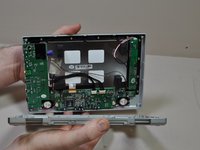
Separate the halves of the case.
-
-
-
-
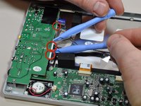
Locate the input/output board on the top left hand corner of the device. It will look like a green circuit board with wires protruding and connecting to the case cover.
-
Using your blue plastic opening tool, disconnect the multicolored wires located on the input/output board. These will be the same multicolored wires that connect the back cover to the input/output board.
-
-
-
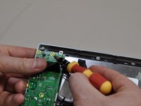
Use two blue plastic opening tools to remove the three wire connectors on the side of the input/output board.
-
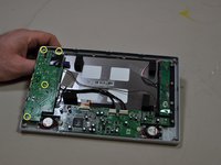
Use a Philips #0 screwdriver to remove the five screws on the board.
-
Lift board from case.
-


To reassemble your device, follow these instructions in reverse order.
Annulla: non ho completato questa guida.
Un'altra persona ha completato questa guida.
Team

Cal Poly, Team 8-14, Maness Winter 2012 Membro di Cal Poly, Team 8-14, Maness Winter 2012
CPSU-MANESS-W12S8G14
4 Membri
8 Guide realizzate