Questa versione può contenere modifiche errate. Passa all'ultima istantanea verificata.
Cosa ti serve
-
Questo passaggio è privo di traduzione. Aiuta a tradurlo
-
Remove the five 7.2 mm Phillips screws at the back of the controller.
-
-
Questo passaggio è privo di traduzione. Aiuta a tradurlo
-
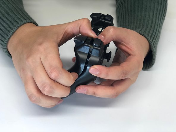
Separate the bottom case from the upper part. All the electronics stay in the upper part.
-
-
Questo passaggio è privo di traduzione. Aiuta a tradurlo
-
Remove the left and right bumper buttons (L1, L2, R1 and R2).
-
-
Questo passaggio è privo di traduzione. Aiuta a tradurlo
-
Remove the rubber underlays of the buttons L1, L2, R1 and R2.
-
-
Questo passaggio è privo di traduzione. Aiuta a tradurlo
-
Take the battery off the PCB (printed circuit board).
-
-
-
Questo passaggio è privo di traduzione. Aiuta a tradurlo
-
Unscrew the remaining 7.2 mm Phillips screw from the PCB.
-
-
Questo passaggio è privo di traduzione. Aiuta a tradurlo
-
Unplug the battery from the PCB by using a pair of pliers as shown in the photo.
-
-
Questo passaggio è privo di traduzione. Aiuta a tradurlo
-
Take the motherboard (PCB) out of the plastic controller case.
-
-
Questo passaggio è privo di traduzione. Aiuta a tradurlo
-
Remove all loose parts from the body. (Consisting of white rubber button underlays, black plastic buttons and a black rubber underlay for the start and select button.)
-
-
Questo passaggio è privo di traduzione. Aiuta a tradurlo
-
Remove the transparent plastic part covering the LED-lights by taking it out with a pair of pliers.
-
-
Questo passaggio è privo di traduzione. Aiuta a tradurlo
-
Remove the thin flexible green PCB by pulling out the black plastic circuit board cover, relatively in the middle the motherboard (the hard PCB) and by pressing click fingers on top of the motherboard.
-
-
Questo passaggio è privo di traduzione. Aiuta a tradurlo
-
Remove the thin flexible green PCB by lifting and pushing the two outer flaps.
-


Annulla: non ho completato questa guida.
Un'altra persona ha completato questa guida.
Team

Delft University of Technology, Team S1-G4, Flipsen Spring 2018 Membro di Delft University of Technology, Team S1-G4, Flipsen Spring 2018
TUD-FLIPSEN-S18S1G4
4 Membri
1 Guida realizzata