Questa versione può contenere modifiche errate. Passa all'ultima istantanea verificata.
Cosa ti serve
-
Questo passaggio è privo di traduzione. Aiuta a tradurlo
-
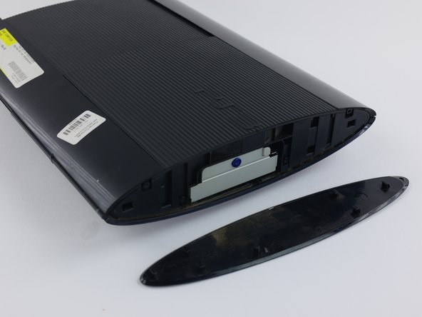
Remove the side HDD bay cover by sliding the panel towards the back of the device.
-
-
Questo passaggio è privo di traduzione. Aiuta a tradurlo
-
Remove all three black 9.8mm long screws with a T-8 security screwdriver.
-
Remove the blue 7.9mm long screw with a Phillips #1 screwdriver.
-
-
Questo passaggio è privo di traduzione. Aiuta a tradurlo
-
On the bottom of the device, pry out the three rubber feet covers with the metal spudger.
-
Remove the four black 36.3mm long screws underneath with a Phillips #1 screwdriver.
-
-
Questo passaggio è privo di traduzione. Aiuta a tradurlo
-
On the top of the device, unlatch the hook on the furthest right beneath the front panel, lift the panel slightly and apply pressure.
-
Unlatch the second right-side hook by sliding a plastic opening tool in the marked area.
-
Slide the panel to the left to unlatch the rest of the hooks.
-
-
-
Questo passaggio è privo di traduzione. Aiuta a tradurlo
-
Remove the back panel by pressing down the tab on the right side of the device, and sliding the panel to the left.
-
-
Questo passaggio è privo di traduzione. Aiuta a tradurlo
-
Remove the five silver 20.8mm long screws with a Phillips #1 screwdriver.
-
Remove the two black 9.9mm long screws in the disc reader with a T-8 security screwdriver.
-
Remove the top black plastic shell.
-
-
Questo passaggio è privo di traduzione. Aiuta a tradurlo
-
Move the optical drive to the side to reveal one of the silver 8.8mm long screws.
-
Remove the two silver 8.8mm long screws on either side with a Phillips #1 screwdriver.
-
-
Questo passaggio è privo di traduzione. Aiuta a tradurlo
-
Remove the cable from the plug and remove the wires from the two plastic hooks.
-
Remove the power supply unit.
-
-
Questo passaggio è privo di traduzione. Aiuta a tradurlo
-
Remove the front white flex-ribbon cable by pulling upward from its base.
-
Remove the black and blue flex-ribbon cable behind it by pulling upward on the black tab, then pulling out the cable.
-
-
Questo passaggio è privo di traduzione. Aiuta a tradurlo
-
Rotate the device 180 degrees.
-
Remove the back white flex-ribbon cable by pulling upward from its base.
-
Remove the optical drive.
-
-
Questo passaggio è privo di traduzione. Aiuta a tradurlo
-
Lift up the free end of the laser lens to separate the two layers.
-
On the bottom of the laser lens, flip up the black plastic latch to remove the flex ribbon cable.
-
-
Questo passaggio è privo di traduzione. Aiuta a tradurlo
-
Remove the 4 rubber bushings.
-
Remove the metal faceplate from the laser lens.
-


Annulla: non ho completato questa guida.
Altre 6 persone hanno completato questa guida.
Team

Cal Poly, Team 34-13, Maness Spring 2016 Membro di Cal Poly, Team 34-13, Maness Spring 2016
CPSU-MANESS-S16S34G13
4 Membri
21 Guide realizzate
6 Commenti
so i did follow this to a tee and not only does the laser not want to work but it keeps makeing this buzzing sound whenever the disk tray is closed
is there something i might be doing wrong
like the video,
Where is the parts purchased from?
Thanks Joe
Laser is KEM-850a. You can order them from ebay. gamesunlimited and ep game supply are good stores. You can also order these from groupvertical.com or sourcleyplus.com
I am replacing the optical drive in my console. But didn't note where the drive ribbon was positioned!? Every video I have found, they just pop right in...my original and replacement drives, have larger receptacles than the ribbon it self. There are at least 5 pins, that don't have (potentially) anything connecting them, to the ribbon. I don't want to randomly place the ribbon in one of the possible (7?) positions and fry something in the process...so where do I connect the smaller ribbon?!