Introduzione
A guide for removing the mirror box of the Pentax LX. This is often required for general maintenance of the camera such as servicing the shutter, removing and replacing the rubber bumpers and cleaning the mirror mechanism. Previous experience with camera repair and a general knowledge of how the camera operates is highly recommended. The guide may not contain every detail and the service manual is necessary for proper adjustment and coupling of all mechanisms during reassembly. Additionally, the wiring in the LX is complex and wire colors may be hard to distinguish. When in doubt, take extra pictures so you can properly reassemble.
Any disassembly of the LX body will compromise the weather sealing. New seals must be reapplied during final reassembly to restore weather proofing.
Cosa ti serve
-
-
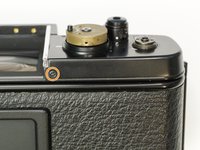
Place a thin tool in the rewind fork and unscrew the topside knob.
-
Remove the washer under the rewind knob.
-
-
-
Remove three #000 5.5 mm screws.
-
Remove exposure compensation dial assembly.
-
Remove washer.
-
Remove rubber seal.
-
-
-
Remove one #00 X mm screw.
-
Remove one #00 2.5 mm screw.
-
-
-
Use a piece of tape wrapped sticky side out to grip the winding lever cover. Turn clockwise to loosen and remove
-
Remove four #000 2.5 mm screws.
-
Use spanners to remove top cover retaining nut.
-
-
-
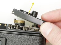
Gently remove the rubber covering around the shutter speed dial.
-
Remove three #000 1.6 mm screws.
-
Remove cover ring.
-
-
-
Remove one #00 2.5 mm screw.
-
Remove one #00 X mm screw.
-
Lift off top cover.
-
-
-
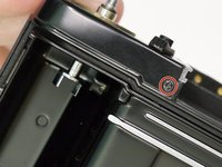
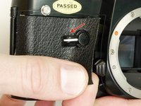
Remove the rubber bumper covering the screw.
-
Remove one #00 1.8 mm screw.
-
Repeat on the other side of the bottom plate (#00 3.0 mm screw).
-
-
-
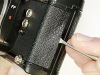
Use isopropyl alcohol to soften the adhesive along the edge of the leatherette.
-
Use a dull spudger or scraper to peel off the covering.
-
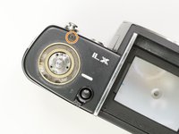
Turn the self timer lever to the 9 o'clock position.
-
Loosen the entire right side leatherette in the same manner, then work it over and around the self timer lever to remove.
-
-
-
-
Remove the two cover plates under the leatherette.
-
They may stick to the covering adhesive and come off on their own.
-
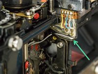
This small plug may also be loose.
-
-
-
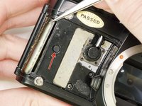
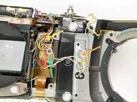
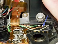
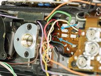
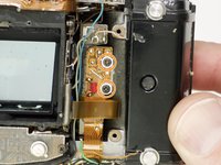
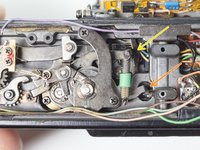
Unsolder one gray wire.
-
Unsolder two yellow wires.
-
Unsolder one blue wire.
-
Unsolder one red wire.
-
-
-
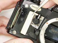
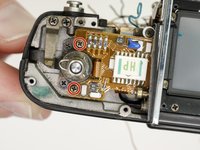
Unscrew four #00 X mm screws.
-
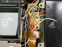
Unsolder one white wire.
-
Unsolder one pink wire.
-
Unsolder one light green wire.
-
Check the mounting points for shim washers. If they are loose, note the position and remove.
-
-
-
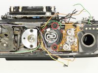
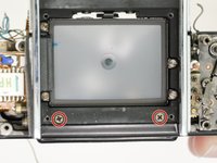
Remove four #000 1.8 mm screws.
-
Remove the light seal frame.
-
-
-
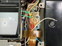
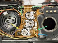
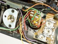
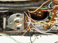
Unsolder one pink wire.
-
Unsolder one purple wire.
-
Unsolder one green wire.
-
Unsolder two yellow wires.
-
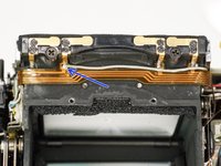
Unsolder two brown wires under the loop of flex cable.
-
Unsolder one gray wire.
-
-
-
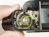
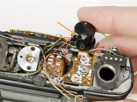
Unscrew three #00 3.0 mm screws.
-
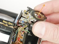
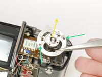
Remove exp/ISO resistor assembly.
-
Remove exp. compensation coupling cam.
-
There are two loose ball bearings that sit in these holes. Do not lose.
-
Installation Note: Push this lever back to properly seat the exposure compensation lock. Check that the flag in the viewfinder is working properly. It should not be visible when dial is set to 1x and pop into view when set to any other value.
-
-
-
Unsolder five black wires.
-
Unsolder two green wires.
-
Unsolder one purple wire.
-
Unsolder one yellow wire.
-
Unsolder one orange wire.
-
Unsolder one light brown wire.
-
-
-
Unsolder one light blue wire (may appear beige).
-
Unsolder one green wire.
-
Unsolder one pink wire.
-
Unsolder one blue wire.
-
Unsolder two black wires.
-
Unsolder one brown wire.
-
-
-
Unsolder one yellow wire.
-
Unsolder one white wire.
-
Unsolder one light blue/teal wire.
-
Unsolder one gray wire.
-
-
-
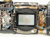
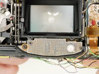
Remove four #00 1.8 mm screws.
-
Lift out bezel with glass attached.
-
-
-
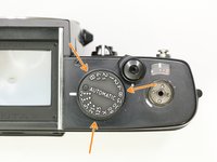
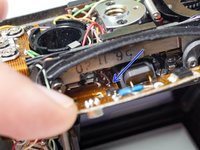
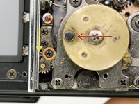
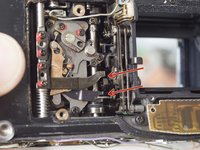
Turn shutter speed selector to 'Auto'.
-
Turn lock lever screw clockwise to loosen. Do not remove.
-
Push lock lever toward the needle indicator gear.
-
Turn lock lever screw counter-clockwise to tighten.
-
-
-
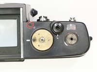
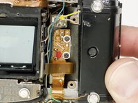
Remove two #00 2.8 mm screws. Remove two loose spacers underneath the PCB.
-
Remove two #00 2.0 mm screws.
-
Remove two #00 2.0 mm screws.
-
-
-
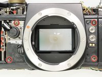
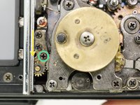
Remove two #00 3.0 mm screws.
-
Remove one #00 5.0 mm screw.
-
Remove mirror box by lifting up then out. Pull slowly and check for snags as you remove.
-
-
-
Before installing the mirror box, the shutter should be wound and the mirror released into the taking position (up against the focusing screen).
-
After mounting the mirror box, make sure all necessary wires are available through the bottom of the camera for soldering.
-
Check for proper coupling of the self timer and the shutter button release.
-
Check that the closing curtain latch sits forward of the mirror return latch.
-
Check that the FP switch lever holds the magnet lever.
-
Select one of the mechanical shutter speeds and test the function of the mirror and shutter. The camera should be capable of a complete exposure cycle at this point.
-


To reassemble your device, follow these instructions in reverse order.
To reassemble your device, follow these instructions in reverse order.
Annulla: non ho completato questa guida.
Un'altra persona ha completato questa guida.
9 Commenti
Hello Sam,
Very nice guide you’ve made here - do you have any advice regarding manual speeds not being able to be adjusted and faster by turning the manual speed pot (it does alter the speed but the pot runs out of adjustment before I am able to get 1 sec to be 1 - it’s around 1,5.)
I have not cleaned and lubed yet, but am thinking a lot about doing so with your comprehensive guide :)
Any advice would be much appreciated here in order to perhaps be spared of unnecessary work :)
My first thought is to make sure you are testing the speeds with film in the camera, although this can be a bit tricky with some testers. For the slow speeds, like 1s, the camera measures the light off the surface of the film and calculates the proper exposure in real time. Without film loaded, it measures the light off the pressure plate or whatever you testing unit puts in the film plane. These are usually "darker" than film and result in artificially long shutter times.
Ah that could definitely be an explanation for my problem, since I was not testing with film in - will definitely have go at that and hopefully that does it - thank you very much for the help :)
Phil810 -
That was the solution to mu problem - thank you again, Sam :)
Phil810 -
Manual mode, both mechanical (>1/60th) and electronically controlled speeds (<1/60th) don't require film to be present. Electronically controlled speeds are adjusted with VRB B, only after shutter curtain speeds are correctly adjusted and the mechanical speeds are correct. If 1/2000th isn't within limits, the high-speed cam required changing. Only in auto is film required.