Questa versione può contenere modifiche errate. Passa all'ultima istantanea verificata.
Cosa ti serve
-
Questo passaggio è privo di traduzione. Aiuta a tradurlo
-
Remove both of the 3 mm screws on the bottom of the camera connected to the side panel.
-
-
Questo passaggio è privo di traduzione. Aiuta a tradurlo
-
Remove the remaining 3 mm screw holding on the side panel and remove the panel entirely.
-
-
Questo passaggio è privo di traduzione. Aiuta a tradurlo
-
On the opposite side of the camera, remove the two 3 mm screws.
-
Remove the bottom side panel and place it with its respective 3 mm screw.
-
-
Questo passaggio è privo di traduzione. Aiuta a tradurlo
-
Remove the front panel (the panel around the lens casing) from the camera.
-
Remove the two ribbon cables connected to the back panel (the panel this the LCD screen) by lifting up on their respective tabs and gently pulling out the cord.
-
Remove the back panel from the camera.
-
-
-
Questo passaggio è privo di traduzione. Aiuta a tradurlo
-
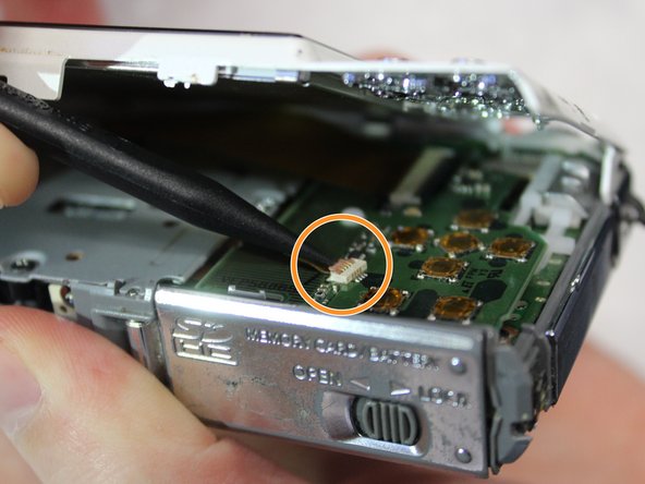
Remove the top control panel (connected to the flash battery) from the camera.
-
-
Questo passaggio è privo di traduzione. Aiuta a tradurlo
-
Unscrew the silver 2mm screw from the protection panel.
-
Unscrew the three black 8mm screws from the protection panel.
-
Remove the protection panel entirely.
-
-
Questo passaggio è privo di traduzione. Aiuta a tradurlo
-
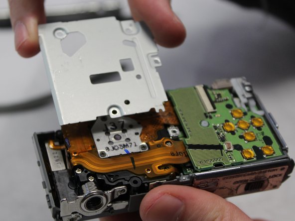
Insert the flat end of a spudger underneath the motherboard and twist. This will disconnect it from the rest of the device.
-
-
Questo passaggio è privo di traduzione. Aiuta a tradurlo
-
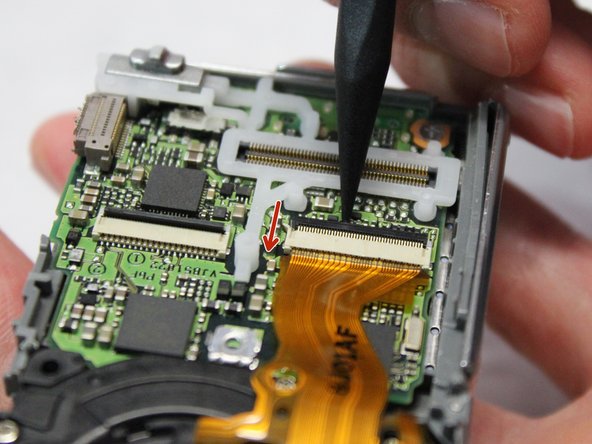
Using the pointed end of a spudger, flip up the two black tabs holding the ribbon cables in place.
-
-
Questo passaggio è privo di traduzione. Aiuta a tradurlo
-
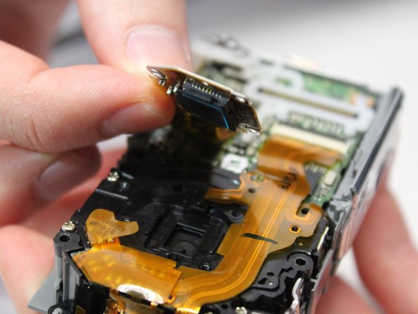
Unscrew the three 3mm screws holding the photoreceptor in place.
-
Lift the photoreceptor and gently pull it to release the now disconnected ribbon cable.
-
-
Questo passaggio è privo di traduzione. Aiuta a tradurlo
-
Gently lift and remove the lens casing, pulling it free from the now disconnected ribbon cable.
-


Team

Baylor, Team S2-G3, Johnson Spring 2018 Membro di Baylor, Team S2-G3, Johnson Spring 2018
BU-JOHNSON-S18S2G3
3 Membri
6 Guide realizzate