Salta al contenuto principale

Questa versione può contenere modifiche errate. Passa all'ultima istantanea verificata.

Cosa ti serve

  1. , Batteria: passo 1, immagine 1 di 2 , Batteria: passo 1, immagine 2 di 2
    • Rimuovi le due viti a croce Phillips che fissano la copertura della batteria al retro della console portatile.

    • Rimuovi la copertura della batteria dal retro del DSi XL.

  2. : passo 2, immagine 1 di 1
    • Solleva la batteria dal DSi XL.

  3. , Scheda Wi-Fi: passo 3, immagine 1 di 2 , Scheda Wi-Fi: passo 3, immagine 2 di 2
    • Solleva la scheda Wi-Fi dalla sua presa sulla scheda madre.

    • Non provare ancora a rimuovere completamente la scheda Wi-Fi. È collegata alla scheda madre tramite un cavo antenna.

  4. : passo 4, immagine 1 di 1
    • Utilizza uno spudger per sollevare il cavo Wi-Fi dalla sua presa sull lato inferiore della scheda Wi-Fi.

  5. , Scheda madre: passo 5, immagine 1 di 1
    • Utilizza uno spudger per sollevare il cavo del microfono dalla scheda madre.

    • Fai leva da sotto il cavo.

  6. : passo 6, immagine 1 di 2 : passo 6, immagine 2 di 2
    • Utilizzando l'estremità piatta di uno spudger, capovolgi il nastro di bloccaggio sul connettore ZIF del cavo a nastro della fotocamera.

    • Utilizza l'estremità appuntita di uno spudger per tirare via il cavo a nastro della fotocamera dal connettore ZIF.

  7. : passo 7, immagine 1 di 2 : passo 7, immagine 2 di 2
    • Utilizzando l'estremità piatta di uno spudger, capovolgi il nastro di bloccaggio sul connettore ZIF del cavo del touchscreen.

    • Con l'estremità appuntita di uno spudger, tira via il cavo del touchscreen dal suo connettore sulla scheda madre.

  8. : passo 8, immagine 1 di 2 : passo 8, immagine 2 di 2
    • Utilizzando l'estremità piatta di uno spudger, capovolgi il nastro di bloccaggio sul connettore ZIF del cavo della retroilluminazione.

    • Con l'estremità appuntita di uno spudger, tira via il cavo della retroilluminazione dal suo connettore sulla scheda madre.

  9. : passo 9, immagine 1 di 2 : passo 9, immagine 2 di 2
    • Utilizzando l'estremità piatta di uno spudger, capovolgi il nastro di bloccaggio sul connettore ZIF del cavo dati del display inferiore.

    • Con l'estremità appuntita di uno spudger, tira il display inferiore del cavo dati dal suo connettore sulla scheda madre.

  10. : passo 10, immagine 1 di 2 : passo 10, immagine 2 di 2
    • Utilizzando l'estremità piatta di uno spudger, capovolgi il nastro di bloccaggio sul connettore ZIF per il cavo del D-Pad/del pulsante di accensione.

    • Con l'estremità appuntita di uno spudger, tira il cavo del D-Pad/del pulsante di accensione dal suo connettore sulla scheda madre.

  11. : passo 11, immagine 1 di 1
    • Utilizzando l'estremità piatta di uno spudger, solleva il cavo della batteria dalla sua presa sulla scheda madre.

  12. : passo 12, immagine 1 di 1
    • Rimuovi le viti che fissano la scheda madre al case superiore:

    • Una sola vite argentata a croce Phillips da 2,5 mm

    • Quattro viti a croce Phillips nere da 3,7 mm

  13. : passo 13, immagine 1 di 1
    • Reindirizza i cavi del microfono e dell'antenna attraverso lo slot della scheda madre.

  14. : passo 14, immagine 1 di 2 : passo 14, immagine 2 di 2
    • Ruota la scheda madre fuori dal case inferiore.

    • La scheda madre non può ancora essere completamente rimossa. È ancora connessa dal cavo a nastro dei dati del display LCD superiore.

  15. : passo 15, immagine 1 di 2 : passo 15, immagine 2 di 2
    • Utilizzando l'estremità piatta di uno spudger, capovolgi il nastro di bloccaggio sul connettore ZIF del cavo dati del display superiore.

    • Con l'estremità appuntita di uno spudger, tira il cavo dati del display superiore dal suo connettore al di sotto della scheda madre.

    • La scheda madre è adesso libera dal case superiore.

  16. Questo passaggio è privo di traduzione. Aiuta a tradurlo

    : passo 16, immagine 1 di 2 : passo 16, immagine 2 di 2
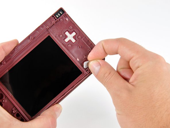
    • With the console still upside-down, open the DSi XL slightly.

    • Push the lower display away from the upper case.

    • Remove the lower display from the DSi XL.

  17. Questo passaggio è privo di traduzione. Aiuta a tradurlo

    : passo 17, immagine 1 di 3 : passo 17, immagine 2 di 3 : passo 17, immagine 3 di 3
    • Turn the DSi XL over and open the display.

    • When re-assembling the device, be sure to re-install the ABXY and Start/Select buttons, as they are likely to fall out once the handheld console is turned over.

    • Use a pushpin to remove the four plastic screw covers on the front bezel.

  18. Questo passaggio è privo di traduzione. Aiuta a tradurlo

    : passo 18, immagine 1 di 1
    • Remove the four 3.5 mm silver Phillips screws securing the rear bezel to the front bezel.

  19. Questo passaggio è privo di traduzione. Aiuta a tradurlo

    : passo 19, immagine 1 di 2 : passo 19, immagine 2 di 2
    • Using two hands, gently slide the rear bezel upwards.

    • The rear bezel will move only about 2 mm.

  20. Questo passaggio è privo di traduzione. Aiuta a tradurlo

    : passo 20, immagine 1 di 2 : passo 20, immagine 2 di 2
    • Insert a spudger into the gap between the front and rear bezel.

    • Rotate the spudger away from the DSi XL, prying the two bezels apart.

  21. Questo passaggio è privo di traduzione. Aiuta a tradurlo

    : passo 21, immagine 1 di 2 : passo 21, immagine 2 di 2
    • In the same manner as described above, continue prying along the top edge of the front and rear bezels.

  22. Questo passaggio è privo di traduzione. Aiuta a tradurlo

    : passo 22, immagine 1 di 1
    • Separate the rear bezel from the front bezel.

    • Do not attempt to completely remove the rear bezel yet. It is still attached to the front bezel by the rear-facing camera.

  23. Questo passaggio è privo di traduzione. Aiuta a tradurlo

    : passo 23, immagine 1 di 1
    • Using the flat end of a spudger, pry the rear camera off the rear bezel.

    • Remove the rear bezel.

  24. Questo passaggio è privo di traduzione. Aiuta a tradurlo

    : passo 24, immagine 1 di 2 : passo 24, immagine 2 di 2
    • Remove the Phillips screw holding the metal securing bracket in place.

    • Lift the metal bracket off the camera.

  25. Questo passaggio è privo di traduzione. Aiuta a tradurlo

    : passo 25, immagine 1 di 2 : passo 25, immagine 2 di 2
    • Lift the Wi-Fi antenna off the front display bezel.

    • De-route the Wi-Fi antenna cable from its grooves at the bottom of the front display bezel.

  26. Questo passaggio è privo di traduzione. Aiuta a tradurlo

    : passo 26, immagine 1 di 3 : passo 26, immagine 2 di 3 : passo 26, immagine 3 di 3
    • Pull the Wi-Fi antenna cable through the right hinge connecting the front bezel and upper case.

    • Use the pointed end of a spudger to guide the connector at the end of the Wi-Fi antenna cable through the hinge.

    • To replace the antenna, use a pair of tweezers to guide the connector through the hinge.

  27. Questo passaggio è privo di traduzione. Aiuta a tradurlo

    : passo 27, immagine 1 di 3 : passo 27, immagine 2 di 3 : passo 27, immagine 3 di 3
    • Close the DSi XL and turn it over.

    • Using a pair of tweezers, pull the microphone out of its housing in the front bezel.

    • De-route the microphone cable, and pull it through the right hinge.

  28. Questo passaggio è privo di traduzione. Aiuta a tradurlo

    : passo 28, immagine 1 di 3 : passo 28, immagine 2 di 3 : passo 28, immagine 3 di 3
    • Using the flat end of a spudger, pry the left speaker out of its socket on the front bezel.

    • De-route the speaker cable along the top edge of the screen.

    • Work carefully and slowly, holding onto the wire and not the speaker itself. The solder joints may break if pulled on too hard.

    • In the same manner described above, remove the right speaker from its socket on the front bezel.

    • Place both speakers on the back of the upper LCD.

  29. Questo passaggio è privo di traduzione. Aiuta a tradurlo

    : passo 29, immagine 1 di 2 : passo 29, immagine 2 di 2
    • Ensuring that the upper LCD does not fall out of the front bezel, turn the DSi XL over.

    • Remove the seven 2.5 mm silver screws securing the power board to the upper case.

    • Lift the power board up off the upper case.

  30. Questo passaggio è privo di traduzione. Aiuta a tradurlo

    : passo 30, immagine 1 di 2 : passo 30, immagine 2 di 2
    • Peel the rubber button pads off the backside of the D-pad and power button.

  31. Questo passaggio è privo di traduzione. Aiuta a tradurlo

    : passo 31, immagine 1 di 2 : passo 31, immagine 2 di 2
    • Open the case slightly.

    • Push the D-pad up through its housing in the upper case. Remove the D-pad.

    • In the same way, remove the power button from the upper case.

  32. Questo passaggio è privo di traduzione. Aiuta a tradurlo

    : passo 32, immagine 1 di 2 : passo 32, immagine 2 di 2
    • Using a pair of tweezers, remove the LED diffuser bracket and the LED diffuser from the upper case of the DSi XL.

  33. Questo passaggio è privo di traduzione. Aiuta a tradurlo

    : passo 33, immagine 1 di 3 : passo 33, immagine 2 di 3 : passo 33, immagine 3 di 3
    • In the following steps, you will be using a spudger to remove the hinge pin from the left side of the DSi XL.

    • Place the tip of a spudger in the LED diffuser compartment, on the face of the clutch hinge.

    • Push the clutch hinge to the left.

    • Some force will be required. You will hear an audible "pop" when the clutch has cleared the lower case. It will move about 0.25".

  34. Questo passaggio è privo di traduzione. Aiuta a tradurlo

    : passo 34, immagine 1 di 2 : passo 34, immagine 2 di 2
    • Lift the left side of the front bezel away from the upper case.

    • Do not lift too far, or else the hinge pin will break. Only lift enough to clear the LED compartment, about 1".

    • Pull the front bezel to the left, separating the front bezel from the upper case.

    • Do not attempt to fully separate the two halves yet. There are still ribbon cables running through the upper case.

  35. Questo passaggio è privo di traduzione. Aiuta a tradurlo

    : passo 35, immagine 1 di 3 : passo 35, immagine 2 di 3 : passo 35, immagine 3 di 3
    • Grasp the camera and upper LCD ribbon cables between your thumb and forefinger, pulling them out of the upper case slightly, slide them down through the slit in the upper case.

    • Rotate the front bezel assembly clockwise so that the ends of the camera and LCD cables slide sideways through the slit in the front bezel.

  36. Questo passaggio è privo di traduzione. Aiuta a tradurlo

    : passo 36, immagine 1 di 2 : passo 36, immagine 2 di 2
    • In order to remove the upper LCD and the cameras from the front bezel, it is helpful to coil the ribbon cables together.

    • Carefully coil the two ribbon cables together, so that the connectors are on the inside of the spool.

    • Wrap the ribbon cables tightly, but not too tight, as bending the connectors will render them inoperable.

  37. Questo passaggio è privo di traduzione. Aiuta a tradurlo

    : passo 37, immagine 1 di 2 : passo 37, immagine 2 di 2
    • Holding the upper LCD and the cameras together, pull the cables through the hinge in the front bezel.

    • Pull slowly, making sure that the cables do not catch on the hinge pin and tear.

    • Uncoil the ribbon cables.

  38. Questo passaggio è privo di traduzione. Aiuta a tradurlo

    : passo 38, immagine 1 di 2 : passo 38, immagine 2 di 2
    • Pull the hollow hinge pin out of the right side of the front bezel.

  39. Questo passaggio è privo di traduzione. Aiuta a tradurlo

    : passo 39, immagine 1 di 2 : passo 39, immagine 2 di 2
    • Push the clutch hinge on the left side of the front bezel through its mount bracket.

    • Remove the clutch hinge.

Linea Traguardo

Altre 3 persone hanno completato questa guida.

Brett Hartt

Membro da: 04/12/10

127.926 Reputazione

143 Guide realizzate

Team

iFixit Membro di iFixit

Staff

135 Membri

17.199 Guide realizzate

0 Commenti

Aggiungi Commento

Visualizza Statistiche:

Ultime 24 Ore: 6

Ultimi 7 Giorni: 45

Ultimi 30 Giorni: 180

Tutti i Tempi: 23,531