Questa versione può contenere modifiche errate. Passa all'ultima istantanea verificata.
Cosa ti serve
-
Questo passaggio è privo di traduzione. Aiuta a tradurlo
-
Using a pair of tweezers, pull the microphone out of its housing in the front bezel.
-
De-route the microphone cable, and pull it through the right hinge.
-
-
Questo passaggio è privo di traduzione. Aiuta a tradurlo
-
Using the flat end of a spudger, pry the left speaker out of its socket on the front bezel.
-
De-route the speaker cable along the top edge of the screen.
-
In the same manner described above, remove the right speaker from its socket on the front bezel.
-
Place both speakers on the back of the upper LCD.
-
-
Questo passaggio è privo di traduzione. Aiuta a tradurlo
-
Remove the seven 2.5 mm silver screws securing the power board to the upper case.
-
Lift the power board up off the upper case.
-
-
Questo passaggio è privo di traduzione. Aiuta a tradurlo
-
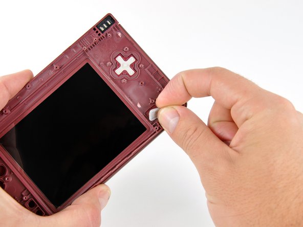
Peel the rubber button pads off the backside of the D-pad and power button.
-
-
-
Questo passaggio è privo di traduzione. Aiuta a tradurlo
-
Push the D-pad up through its housing in the upper case. Remove the D-pad.
-
In the same way, remove the power button from the upper case.
-
-
Questo passaggio è privo di traduzione. Aiuta a tradurlo
-
Using a pair of tweezers, remove the LED diffuser bracket and the LED diffuser from the upper case of the DSi XL.
-
-
Questo passaggio è privo di traduzione. Aiuta a tradurlo
-
Place the tip of a spudger in the LED diffuser compartment, on the face of the clutch hinge.
-
Push the clutch hinge to the left.
-
-
Questo passaggio è privo di traduzione. Aiuta a tradurlo
-
Lift the left side of the front bezel away from the upper case.
-
Pull the front bezel to the left, separating the front bezel from the upper case.
-
-
Questo passaggio è privo di traduzione. Aiuta a tradurlo
-
Grasp the camera and upper LCD ribbon cables between your thumb and forefinger, pulling them out of the upper case slightly, slide them down through the slit in the upper case.
-
Rotate the front bezel assembly clockwise so that the ends of the camera and LCD cables slide sideways through the slit in the front bezel.
-
-
Questo passaggio è privo di traduzione. Aiuta a tradurlo
-
Carefully coil the two ribbon cables together, so that the connectors are on the inside of the spool.
-
-
Questo passaggio è privo di traduzione. Aiuta a tradurlo
-
Holding the upper LCD and the cameras together, pull the cables through the hinge in the front bezel.
-
Uncoil the ribbon cables.
-