Questa versione può contenere modifiche errate. Passa all'ultima istantanea verificata.
Cosa ti serve
-
-
Svita le due viti a croce Philips che fissano il copribatteria al case inferiore.
-
Prendi il copribatteria e sollevalo dal case inferiore.
-
-
-
Usando uno spudger (o un'unghia), solleva la batteria dalla parte superiore.
-
Prendi la batteria e rimuovila dal DSi.
-
-
-
Ci sono due viti nascoste sotto i due gommini cerchiati in rosso.
-
Usa la punta dello spudger per estrarre i due gommini dal case inferiore.
-
-
-
Inserisci lo spudger tra il case inferiore e il pannello inferiore vicino all'angolo in alto a destra del DSi.
-
Passa delicatamente lo spudger lungo il margine del case esterno, creando uno spazio tra il case e il dispositivo.
-
Continua a passare lo spudger intorno al dispositivo fino a separare il case inferiore quasi del tutto.
-
-
-
Questo passaggio è privo di traduzione. Aiuta a tradurlo
-
Pull the Wi-Fi board away from the motherboard by its edge closest to the headphone jack.
-
-
Questo passaggio è privo di traduzione. Aiuta a tradurlo
-
Pry the Wi-Fi antenna connector straight up from its socket on the Wi-Fi board.
-
-
Questo passaggio è privo di traduzione. Aiuta a tradurlo
-
Use the tip of a spudger to pry the power board connector out of its socket on the motherboard.
-
-
Questo passaggio è privo di traduzione. Aiuta a tradurlo
-
Use your fingernail or the edge of a plastic opening tool to flip up the retaining flap on the following three ZIF sockets:
-
Lower touchscreen cable
-
Lower LCD cable
-
Power board cable
-
After flipping up the locking tabs on all three sockets, use your fingers or a pair of tweezers to gently pull the cables straight out of their sockets.
-
-
Questo passaggio è privo di traduzione. Aiuta a tradurlo
-
Use your fingernail or the edge of a plastic opening tool to carefully flip up the touchscreen ribbon cable retaining flap.
-
Use the tip of a spudger to pull the touchscreen ribbon cable straight out of its socket.
-
-
Questo passaggio è privo di traduzione. Aiuta a tradurlo
-
Use your fingernail or the edge of a plastic opening tool to carefully flip up the dual camera ribbon cable retaining flap.
-
Use the tip of a spudger to pull the dual camera ribbon cable straight out of its socket.
-
-
Questo passaggio è privo di traduzione. Aiuta a tradurlo
-
With the tip of a spudger, Pry the microphone antenna up off its socket on the motherboard.
-
-
Questo passaggio è privo di traduzione. Aiuta a tradurlo
-
Remove the following four Phillips screws securing the motherboard to the DSi framework.
-
Three longer screws.
-
One short screw.
-
Pull the microphone and Wi-Fi antenna cables out of the notch cut into the motherboard near the headphone jack.
-
-
Questo passaggio è privo di traduzione. Aiuta a tradurlo
-
Slightly lift the motherboard upwards to reveal the upper LCD ribbon cable above the ABXY buttons .
-
Use your fingernail or the edge of a plastic opening tool to carefully flip up the upper LCD ribbon cable retaining flap.
-
Remove the motherboard from the DSi.
-
-
Questo passaggio è privo di traduzione. Aiuta a tradurlo
-
Use the tip of a spudger to pry the metal backing of the lower LCD up from the DSi's framework.
-
Lift the lower LCD assembly out of the DSi.
-
-
Questo passaggio è privo di traduzione. Aiuta a tradurlo
-
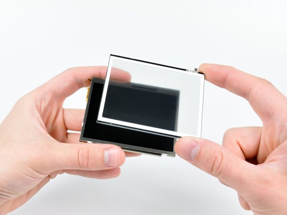
Insert the edge of a plastic opening tool between the lower touchscreen and the lower LCD.
-
Carefully run the edge of the opening tool along the perimeter of the touchscreen to detach it from the lower LCD.
-
Remove the touchscreen from the lower LCD.
-
Lower LCD remains.
-


Annulla: non ho completato questa guida.
Altre 17 persone hanno completato questa guida.

3 Commenti
On Step 9 please add something like this to the description. I didn’t fully understand what was said and i ended up breaking my power connector off the motherboard. I luckily went to Ebay and someone had a replacement thankfully that i was able to solder back on the motherboard. ——————To remove the power wire connector off the motherboard use a small flathead screwdriver to push the white part of the connector straight up. If you try to pull it back like a standard connector it will break! ————-
Hello! I have a DSi with a missing lower display. It won’t turn on (even pluged in). Can anyone tell me if it’s supposed to turn on with the lower display missing? If it is not supposed to turn on without the lower display, then I can buy a replacement display so it probably work, but if it supposed to turn on even without the lower display, then there is some extra problem there.