Questa versione può contenere modifiche errate. Passa all'ultima istantanea verificata.
Cosa ti serve
-
-
Svita le due viti a croce Philips che fissano il copribatteria al case inferiore.
-
Prendi il copribatteria e sollevalo dal case inferiore.
-
-
-
Usando uno spudger (o un'unghia), solleva la batteria dalla parte superiore.
-
Prendi la batteria e rimuovila dal DSi.
-
-
-
Ci sono due viti nascoste sotto i due gommini cerchiati in rosso.
-
Usa la punta dello spudger per estrarre i due gommini dal case inferiore.
-
-
-
Inserisci lo spudger tra il case inferiore e il pannello inferiore vicino all'angolo in alto a destra del DSi.
-
Passa delicatamente lo spudger lungo il margine del case esterno, creando uno spazio tra il case e il dispositivo.
-
Continua a passare lo spudger intorno al dispositivo fino a separare il case inferiore quasi del tutto.
-
-
Questo passaggio è privo di traduzione. Aiuta a tradurlo
-
Pull the Wi-Fi board away from the motherboard by its edge closest to the headphone jack.
-
-
Questo passaggio è privo di traduzione. Aiuta a tradurlo
-
Pry the Wi-Fi antenna connector straight up from its socket on the Wi-Fi board.
-
-
Questo passaggio è privo di traduzione. Aiuta a tradurlo
-
Use the tip of a spudger to pry the power board connector out of its socket on the motherboard.
-
-
-
Questo passaggio è privo di traduzione. Aiuta a tradurlo
-
Use your fingernail or the edge of a plastic opening tool to flip up the retaining flap on the following three ZIF sockets:
-
Lower touchscreen cable
-
Lower LCD cable
-
Power board cable
-
After flipping up the locking tabs on all three sockets, use your fingers or a pair of tweezers to gently pull the cables straight out of their sockets.
-
-
Questo passaggio è privo di traduzione. Aiuta a tradurlo
-
Use your fingernail or the edge of a plastic opening tool to carefully flip up the touchscreen ribbon cable retaining flap.
-
Use the tip of a spudger to pull the touchscreen ribbon cable straight out of its socket.
-
-
Questo passaggio è privo di traduzione. Aiuta a tradurlo
-
Use your fingernail or the edge of a plastic opening tool to carefully flip up the dual camera ribbon cable retaining flap.
-
Use the tip of a spudger to pull the dual camera ribbon cable straight out of its socket.
-
-
Questo passaggio è privo di traduzione. Aiuta a tradurlo
-
With the tip of a spudger, Pry the microphone antenna up off its socket on the motherboard.
-
-
Questo passaggio è privo di traduzione. Aiuta a tradurlo
-
Remove the following four Phillips screws securing the motherboard to the DSi framework.
-
Three longer screws.
-
One short screw.
-
Pull the microphone and Wi-Fi antenna cables out of the notch cut into the motherboard near the headphone jack.
-
-
Questo passaggio è privo di traduzione. Aiuta a tradurlo
-
Slightly lift the motherboard upwards to reveal the upper LCD ribbon cable above the ABXY buttons .
-
Use your fingernail or the edge of a plastic opening tool to carefully flip up the upper LCD ribbon cable retaining flap.
-
Remove the motherboard from the DSi.
-
-
Questo passaggio è privo di traduzione. Aiuta a tradurlo
-
Use the tip of a spudger to pry the metal backing of the lower LCD up from the DSi's framework.
-
Lift the lower LCD assembly out of the DSi.
-
-
Questo passaggio è privo di traduzione. Aiuta a tradurlo
-
Use a pushpin to remove the four plastic screw covers (highlighted in red) on the front bezel.
-
-
Questo passaggio è privo di traduzione. Aiuta a tradurlo
-
Remove the four Phillips screws securing the rear bezel to the front bezel.
-
-
Questo passaggio è privo di traduzione. Aiuta a tradurlo
-
Using two hands, gently slide the rear bezel upwards.
-
Lift the rear bezel straight up out of the DSi.
-
-
Questo passaggio è privo di traduzione. Aiuta a tradurlo
-
De-route the microphone and Wi-Fi antenna cables through the opening located on the bottom DSi's framework.
-
-
Questo passaggio è privo di traduzione. Aiuta a tradurlo
-
Remove the five Phillips screws securing the power board to the DSi's framework.
-
Lift and remove the power board from the DSi.
-
-
Questo passaggio è privo di traduzione. Aiuta a tradurlo
-
Push the metal hinge pin inward on the D-pad side of the front lower panel with the tip of a spudger.
-
The pin should move about 3 mm and stop. It is not necessary to try to completely remove the pin.
-
-
Questo passaggio è privo di traduzione. Aiuta a tradurlo
-
Slightly detach the lower and upper halves of the DSi.
-
De-route the upper LCD and dual camera ribbon cables through the slit near the ABXY side of the front lower panel.
-
Separate the lower and upper halves from each other.
-
-
Questo passaggio è privo di traduzione. Aiuta a tradurlo
-
Using your fingers, grasp the microphone cable and remove it from the front bezel assembly.
-
The microphone will likely pop out of its housing, so it is probably easier to completely remove it at this point.
-
De-route the Wi-Fi antenna cable through the hinge.
-
-
Questo passaggio è privo di traduzione. Aiuta a tradurlo
-
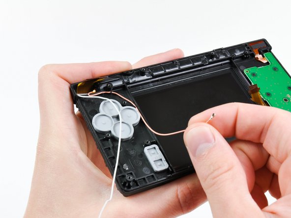
Tightly coil the display and dual camera ribbon cables enough to push them through the steel hinge tube.
-
Remove the steel hinge tube.
-
Carefully push both coiled ribbon cables through the tube molded into the front upper panel.
-
-
Questo passaggio è privo di traduzione. Aiuta a tradurlo
-
Pry the front-facing camera straight up out of its housing in the front bezel.
-
-
Questo passaggio è privo di traduzione. Aiuta a tradurlo
-
Lift the rear-facing out of its housing in the front bezel.
-
Remove the dual camera cable assembly from the DSi.
-


Annulla: non ho completato questa guida.
Altre 4 persone hanno completato questa guida.

3 Commenti
I have a weird question: If I remove the cameras, and reassemble the device without them, will it still work?
It most likely will. My DSi is missing its camera assembly and works fine. Minus the features of the camera.
Elijah -