Questa versione può contenere modifiche errate. Passa all'ultima istantanea verificata.
Cosa ti serve
-
-
Posiziona il tuo dispositivo sottosopra e individua il compartimento della batteria.
-
Trova la vite Phillips che tiene ferma la cover della batteria sull'angolo in basso a destra del dispositivo.
-
-
Questo passaggio è privo di traduzione. Aiuta a tradurlo
-
Remove the following seven screws that secure the lower case to the DS Lite:
-
Three silver tri-wing screws (5mm long)
-
One black tri-wing screw (4mm)
-
Two gold Phillips screws (4mm)
-
One silver Phillips screw (3mm)
-
Do not remove the silver PH screw (3mm) in the battery compartment yet. It holds the main PCB in place.
-
-
Questo passaggio è privo di traduzione. Aiuta a tradurlo
-
On the front edge of the Nintendo DS between the headphone jack plug and volume controls remove the plastic insert (or cartridge) from the lower slot (Slot 2).
-
-
Questo passaggio è privo di traduzione. Aiuta a tradurlo
-
Flip the unit over so that it is facing right-side up.
-
Use a spudger to pry open the gap between the bottom case and the front panel. Work all the way around the case until the panel is free.
-
Avoid touching the L and R shoulder buttons, because they easily detach and are difficult to reassemble. Keep the bottom case flat against your workbench to help hold the shoulder buttons in place.
-
-
Questo passaggio è privo di traduzione. Aiuta a tradurlo
-
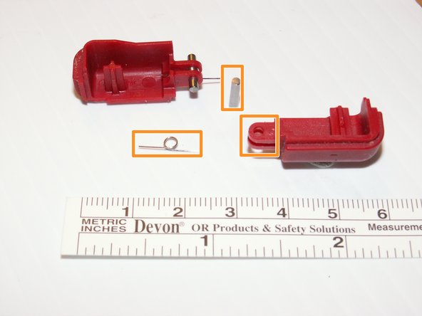
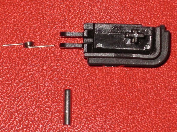
Carefully separate the two pieces by hand.
-
The two shoulder buttons are made up of three pieces -- the plastic button, a pin, and a spring. If they accidentally pop out while you are working, study the picture and make sure you put the spring in the correct position.
-
-
-
Questo passaggio è privo di traduzione. Aiuta a tradurlo
-
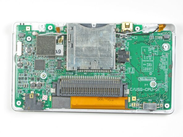
Locate the two screws that attach the logic board to the device.
-
Unscrew the two Phillips head screws.
-
-
Questo passaggio è privo di traduzione. Aiuta a tradurlo
-
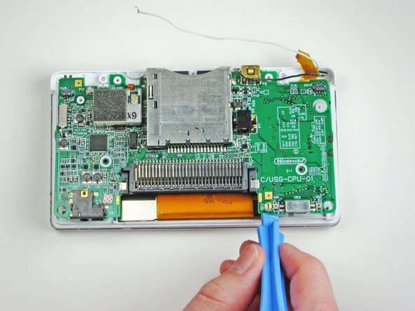
With a plastic opening tool, gently separate the logic board from the device base.
-
-
Questo passaggio è privo di traduzione. Aiuta a tradurlo
-
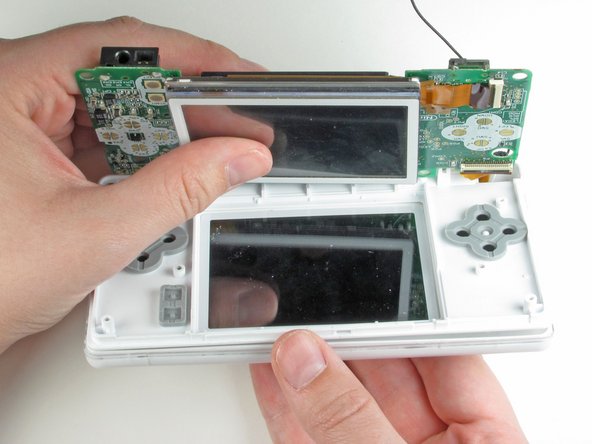
Flip the logic board over so that the touch screen is facing up.
-
Using metal tweezers, carefully disconnect the other ribbon cable that connects the touch screen with the logic board.
-
-
Questo passaggio è privo di traduzione. Aiuta a tradurlo
-
Using one finger nail or the plastic opening tool, carefully lift the brown securing flap of the connector. Then disconnect the ribbon cable that connects the logic board to the upper screen.
-
-
Questo passaggio è privo di traduzione. Aiuta a tradurlo
-
Remove the two Phillips-head screws that hold the hinge in place.
-
Open the system up (just like if you were about to use it normally).
-
-
Questo passaggio è privo di traduzione. Aiuta a tradurlo
-
After opening it, carefully unhinge them from each other by sliding the bottom piece to the left and the top piece to the right.
-
-
Questo passaggio è privo di traduzione. Aiuta a tradurlo
-
Using a push pin, remove the four rubber bumpers located at the corners of the top screen.
-
After removing the LEDs and pulling apart the hinge, remove the round hinge shaft. This should be in the top screen piece.
-
-
Questo passaggio è privo di traduzione. Aiuta a tradurlo
-
Unscrew the four Phillips-head screws and remove the top panel.
-
-
Questo passaggio è privo di traduzione. Aiuta a tradurlo
-
Carefully remove the two speakers and the green wireless card from the top panel.
-
-
Questo passaggio è privo di traduzione. Aiuta a tradurlo
-
Remove the screen by orienting it face down and pushing up on the screen from underneath.
-
-
Questo passaggio è privo di traduzione. Aiuta a tradurlo
-
Carefully slide the ribbon cable through the clip.
-
-
Questo passaggio è privo di traduzione. Aiuta a tradurlo
-
The speakers are soldered to the top screen flex assembly. You may desolder a broken speaker and solder a working speaker on, or you may replace the speakers together with the display assembly.
-


Annulla: non ho completato questa guida.
Un'altra persona ha completato questa guida.
Team

Cal Poly, Team 16-30, Maness Winter 2010 Membro di Cal Poly, Team 16-30, Maness Winter 2010
CPSU-MANESS-W10S16G30
4 Membri
24 Guide realizzate