Questa versione può contenere modifiche errate. Passa all'ultima istantanea verificata.
Cosa ti serve
-
Questo passaggio è privo di traduzione. Aiuta a tradurlo
-
Remove the five 3 mm T3 Torx screws from the headphone jack/speaker assembly.
-
-
Questo passaggio è privo di traduzione. Aiuta a tradurlo
-
Insert a spudger under the panhandle of the headphone jack/speaker assembly and pry it up from its recess.
-
Remove the headphone jack/speaker assembly.
-
-
Questo passaggio è privo di traduzione. Aiuta a tradurlo
-
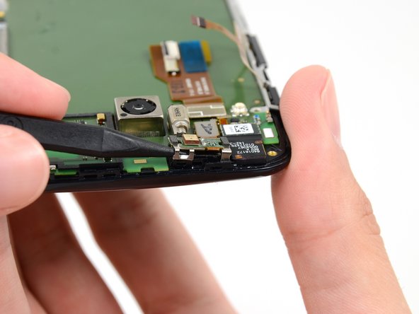
Push the tip of a spudger under the microphone assembly clip to free it from the earpiece speaker.
-
-
Questo passaggio è privo di traduzione. Aiuta a tradurlo
-
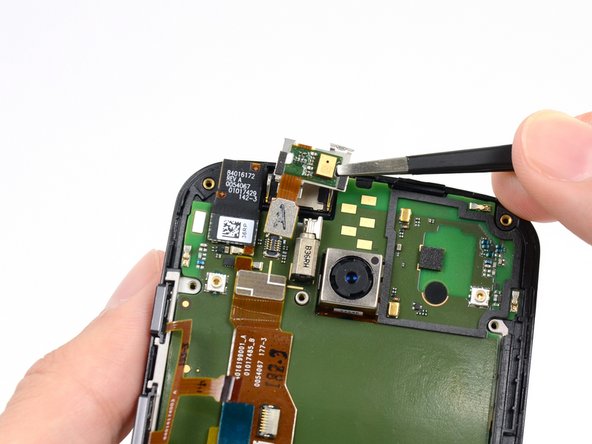
Use the flat end of a spudger to free the microphone assembly cable connector.
-
Use tweezers to remove the microphone assembly.
-
-
-
Questo passaggio è privo di traduzione. Aiuta a tradurlo
-
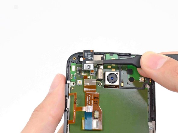
Disconnect the front-facing camera cable connector.
-
Remove the front-facing camera from its recess with a pair of tweezers.
-
-
Questo passaggio è privo di traduzione. Aiuta a tradurlo
-
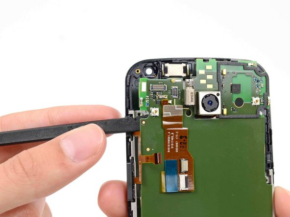
Remove the final two 3 mm T3 Torx screws from the SIM slot bracket.
-
-
Questo passaggio è privo di traduzione. Aiuta a tradurlo
-
Remove the SIM slot bracket from the motherboard.
-
-
Questo passaggio è privo di traduzione. Aiuta a tradurlo
-
Insert the flat end of a spudger under the motherboard above the button assembly cable, and pry it out of the phone.
-
-
Questo passaggio è privo di traduzione. Aiuta a tradurlo
-
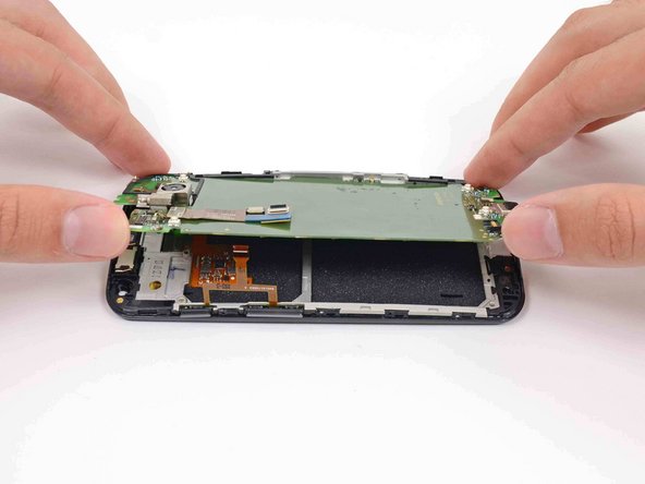
Gently lift the motherboard out of the phone, rotating it from the SIM slot edge of the phone.
-
-
Questo passaggio è privo di traduzione. Aiuta a tradurlo
-
Use the flat end of a spudger to flip the retaining tab on the display cable ZIF connector.
-
Carefully pull the display cable out of its connector as you remove the motherboard from the display assembly.
-