Introduzione
At 2017 MiniWare released TS100 soldering iron. With portable design, temperature control, tips with inductive heating (they warm up very fast and was a novelty 7 years ago), wide power voltage range (12-24V) via standard 5.5x2.1mm Jack connector and open source design (firmware and schematics are openly available) and very affordable price (aprox. 80 USD/EUR on release) it became immensely popular in EE and RC hobbyist community. I still use it as my field iron for repairs outside home.
TS100 has small, but bright and crisp monochrome 0.69" OLED display with 96x16 pixel resolution. Display module contain the Adafruit SSD1306 compatible OLED display and I2C interface. Unfortunately first OLED screen generations was short-lived and this display was not an exception. After 7 years due to burn-in my iron screen became too dark to see something. Now it is time to replace it.
In this guide I will tell about TS100 display replacing steps. And some caveats and issues worth to know and how to avoid them.
Cosa ti serve
-
-
With hex screwdriver or bundled hex key remove two tip retention screws. Pull the tip out.
-
Remove grounding screw.
-
With prying tool carefully open the soldering iron handle casing, starting from tip socket side. Try to avoid breaking the holding pins near display edges at both casing sides.
-
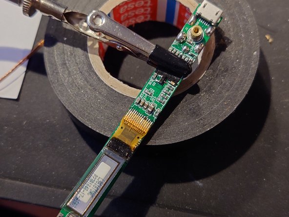
Carefully pull out the small controller chip board near power and MicroUSB sockets.
-
With Philips #00 screwdriver remove two contact clamps at tip socket side.
-
With a help of prying tool carefully pull out the main circuit board, starting from tip socket side.
-
-
-
Put tweezer tips between display module and two-sided adhesive sponge cushion between display and circuit board at free display end. Keep sponge in place and very carefully wiggle the display module upwards. It should come off the sponge with sponge remaining intact. Do the same with second sponge at flat cable side.
-
-
-
Put the flux over flat display cable contact soldering line. I marked it with green arrow at second photo. Turn the soldering iron to 300C (570F) degrees. Heat the soldering line from one side and with tweezers carefully pull the loosened cable away from circuit board.
-
After cable removing clear solder remains from pads with desoldering braid. Clear the board around pads with cotton bud, soaked in PCB cleaner or isopropyl alcohol.
-
-
-
If during cable removal one or both dead-end pads lifted or got torn off, it is not complete failure yet. You have two options:
-
If pad is lifted, carefully arrange it in old position - different color area (yellowish, not green) under the pad. Put a dab of solder paste over it. Then carefully put desoldering braid above it, warm the spot for few seconds and let it cool off. Soldering paste will glue the pad back in the place. Clean the area afterwards.
-
If pad is completely torn off, inspect the area directly behind it where track from pad went further to small black resistor side. With scalpel carefully scrape off the green lacquer in 1mm length to reveal track copper. Put flux over it and tin the cleared track area. Clean the area afterwards.
-
-
-
-
Put a line of flux paste over pads and flat cable end.
-
Take the display module with face side down. Put the flat cable on cleaned pads on circuit board. Arrange the cable over pads to left free pad area a little less than 1mm from the left side (in second photo).
-
Set soldering iron temperature to 270C (520F). Tin the soldering iron and solder the cable to the board.
-
-
-
Inspect the cable soldering. If some pads and cable pins are shorted with solder bridges, put flux paste around the spot and remove excess solder with clean soldering iron tip. If necessary - with a help of desoldering braid.
-
Clear the board around pads with cotton bud, soaked in PCB cleaner or isopropyl alcohol.
-
-
-
With a piece of jump wire or thin regular wire (AWG32 and thinner) connect the display cable pin above torn pad and related tinned track area (from step 4).
-
Put a drop of flux paste above this. Carefully solder both wire ends to cable and track while keeping the wire in place with tweezers.
-
Cut the free wire left behind track soldering with a scalpel.
-
Clean the area.
-
-
-
Connect the controller chip board to the main circuit board.
-
Plug the power supply or an USB cable with MicroUSB connector into appropriate connector on main circuit board.
-
If repair was successful, either Miniware logo with subsequent "Press ..." or "CONFIG" (when USB cable is plugged into MicroUSB port) will appear in the display screen.
-
-
-
Prepare two adhesive EVA sponge cushions in approx. 10mm x 5mm size. Put them under the display module at both ends.
-
Stick the display module above sponge pads. Free module end must be at the spot with a perpendicular line on the board before a row of little back resistors. Display module screen must lie strictly in parallel with circuit board.
-
Insert the circuit board in casing, starting from power connector side. Plug in the power and check if display screen is arranged strictly in parallel with the glass window at the casing face side circuit board. If not, take the board out and correct the display module placement. If needed, repeat till screen is arranged correctly.
-
-
-
Insert the circuit board in casing, starting from power connector side. Before inserting the opposite board end put the tip grounding ring to the end of board with two prongs to board side below the board.
-
Insert back two tip contact clamps. The clamp with wider bottom is located more inside the board. Both clamps have fixing pins at the opposite end of screw hole that must go in appropriate holes in the board. Screw the pads to the board.
-
Inspect are the small controller board firmly sit in the place. If board is loose, carefully push it in till it stop.
-
Install the casing cover starting from the power socket side. Before closing it pull inserted bit outwards to make tip grounding ring stand exactly along the socket wall without free space between. Push the cover - it must freely move inwards over the ring. When it happen, pull the helper bit out and push the cover till end to close it.
-
Put back casing screws. The long screw into a hole with grounding symbol. Both short tip retention screws - to holes around the tip socket.
-
Insert back the soldering iron tip. Fasten it with retention screws.
-
-
-
Plug the power in the soldering iron. See the bright text on replaced display screen and feel happy.
-


TS100 soldering iron display module replacing is not very hard repair. Even easier if you have previous soldering experience and tools for work with microelectronics. Do not hesitate to do it if your iron display fail due to old age. Be careful and do not skimp on flux paste - it is expendable anyway ;)
TS100 soldering iron display module replacing is not very hard repair. Even easier if you have previous soldering experience and tools for work with microelectronics. Do not hesitate to do it if your iron display fail due to old age. Be careful and do not skimp on flux paste - it is expendable anyway ;)
