Questa versione può contenere modifiche errate. Passa all'ultima istantanea verificata.
Cosa ti serve
-
Questo passaggio è privo di traduzione. Aiuta a tradurlo
-
Remove the plastic screw cover located on the bottom of the device. Insert a small flat-headed screwdriver into one side of the cover and gently ease it out. Repeat on the other side.
-
You will need a #00 Phillips screwdriver to remove the two 2.6 mm screws that are exposed.
-
-
Questo passaggio è privo di traduzione. Aiuta a tradurlo
-
Use the blue plastic opening tool to slowly work your way around the edges of the case, releasing the front plate from the bottom case.
-
-
Questo passaggio è privo di traduzione. Aiuta a tradurlo
-
Turn the Zune over so the screen faces downward. This will ensure the battery does not fall out and pull on the cable.
-
Pry up from the bottom of the Zune because the headphone jack will not allow you to remove the back case in one pull. You must slide the case up and away from the rest of the Zune.
-
-
Questo passaggio è privo di traduzione. Aiuta a tradurlo
-
Use the small flat head screw driver to gently lift the brown clamp.
-
The clamp will release the battery ribbon cable from the logic board, freeing the battery.
-
-
Questo passaggio è privo di traduzione. Aiuta a tradurlo
-
Now the back cover is off and the battery is removed, so the hard drive is clearly visible.
-
There are four 4.2 mm screws securing the hard drive to the logic board.
-
Remove all four screws using a Phillips #00 screwdriver.
-
-
-
Questo passaggio è privo di traduzione. Aiuta a tradurlo
-
Carefully tilt the hard drive up from the logic board.
-
-
Questo passaggio è privo di traduzione. Aiuta a tradurlo
-
Flip the hard drive over the top to expose the ribbon cable.
-
-
Questo passaggio è privo di traduzione. Aiuta a tradurlo
-
The ribbon cable is held in place by a black latch on the hard drive.
-
Using a small flat head screwdriver, flip the black latch up 90 degrees.
-
-
Questo passaggio è privo di traduzione. Aiuta a tradurlo
-
Carefully detach the ribbon cable from the hard drive.
-
Now you have completely detached the hard drive.
-
-
Questo passaggio è privo di traduzione. Aiuta a tradurlo
-
The ribbon cable for the button sensor pad is attached with a small clamp to the bottom left corner of the logic board.
-
Use a small flathead screwdriver to lift the brown clasp and remove the ribbon cable.
-
-
Questo passaggio è privo di traduzione. Aiuta a tradurlo
-
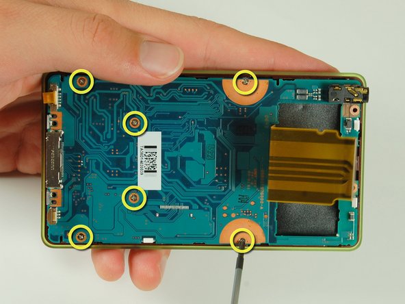
With a Philips #00 screwdriver, remove the six 4.2 mm screws that attach the logic board to the front plate.
-
-
Questo passaggio è privo di traduzione. Aiuta a tradurlo
-
Carefully lift the logic board off of the front plate.
-
The logic board is now free.
-
Follow the LCD repair guide to detach LCD display from logic board.
-
-
Questo passaggio è privo di traduzione. Aiuta a tradurlo
-
The button assembly is made up of three layers, stacked on two plastic pins protruding from the front plate.
-
Unscrew the two plastic pins and the four metal screws with the Philips #00 screwdriver.
-
-
Questo passaggio è privo di traduzione. Aiuta a tradurlo
-
Remove the metal backing plate.
-
Remove the paper shield with tweezers.
-


Annulla: non ho completato questa guida.
Altre 3 persone hanno completato questa guida.
