Questa versione può contenere modifiche errate. Passa all'ultima istantanea verificata.
Cosa ti serve
-
Questo passaggio è privo di traduzione. Aiuta a tradurlo
-
Start by turning the computer around, and remove this #0 Phillips Screw.
-
-
Questo passaggio è privo di traduzione. Aiuta a tradurlo
-
Now lift these two clips, and slowly pivot the case up.
-
You can now seperate the top of the computer from the rest of the machine.
-
-
-
Questo passaggio è privo di traduzione. Aiuta a tradurlo
-
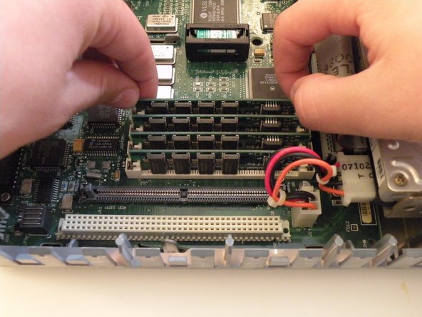
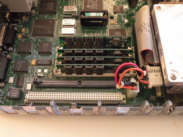
The IIsi uses 4 30-Pin SIMMs (Installed in pairs of 2) for a maximum ram capacity of 65MB. It has 1MB soldered to the logic board as well.
-
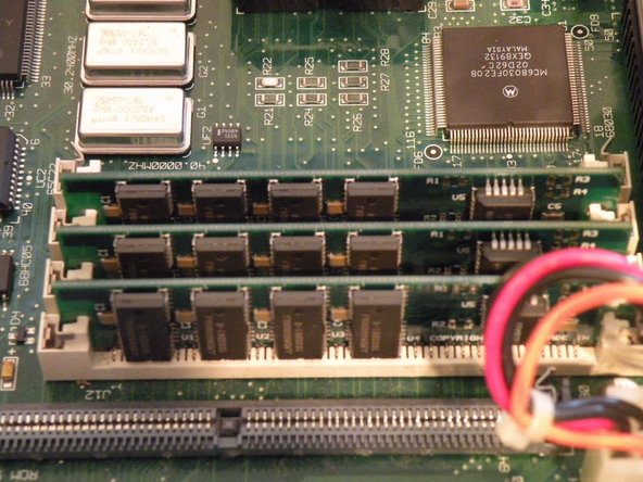
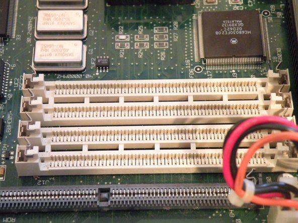
Start with this SIMM. Push these 2 metal tabs outward, then push the ram forward. It can then be lifted out. You have to remove the SIMMs in order, starting with the one you just removed. You can then work your way through all of them.
-


Annulla: non ho completato questa guida.
Altre 4 persone hanno completato questa guida.

Team
