Questa versione può contenere modifiche errate. Passa all'ultima istantanea verificata.
Cosa ti serve
-
-
Rimuovere le otto viti con testa a croce da 4 mm che fissano il case inferiore al MacBook.
-
-
-
Mediante l'estremità piatta di un inseritore, sollevare il connettore del cavo della batteria dal connettore femmina sulla scheda logica tirandolo verso l'alto.
-
-
-
Rimuovere le viti seguenti dal lato con unità ottica della presa posteriore:
-
Due viti Torx T8 da 10 mm
-
Due viti con testa a croce da 5 mm
-
-
Questo passaggio è privo di traduzione. Aiuta a tradurlo
-
Remove the single 3 mm Phillips screw securing the AirPort/Bluetooth antenna ground strap to the rear speaker.
-
-
Questo passaggio è privo di traduzione. Aiuta a tradurlo
-
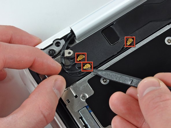
Use the tip of a spudger to pry the AirPort and Bluetooth antenna connectors (3 total) up off the AirPort/Bluetooth card.
-
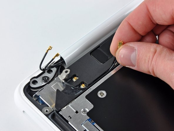
De-route the long antenna from its channel in the rear speaker housing.
-
-
Questo passaggio è privo di traduzione. Aiuta a tradurlo
-
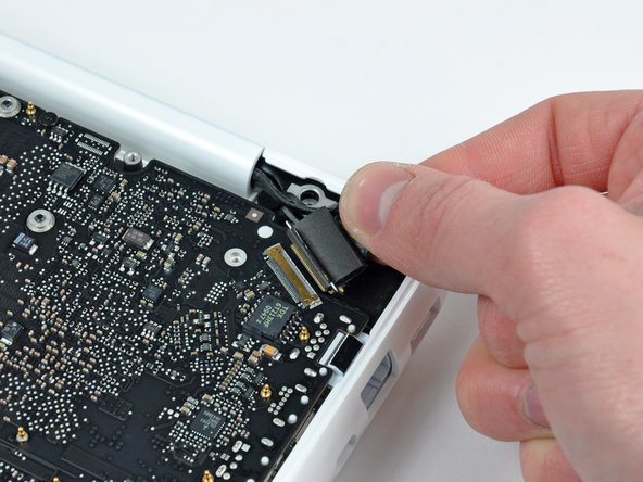
Grab the plastic pull tab secured to the display data cable lock and rotate it toward the DC-In side of the computer.
-
There is also a thin metal lock clip under the plastic tab that has to be released ( Use the tip of a spudger ) before you can disconnect the display data cable.
-
-
Questo passaggio è privo di traduzione. Aiuta a tradurlo
-
Gently pull the display data cable connector away from its socket on the logic board.
-
-
Questo passaggio è privo di traduzione. Aiuta a tradurlo
-
Open your MacBook so the display is perpendicular to the upper case.
-
Place your opened MacBook on a table as pictured.
-
While holding the display and upper case together with your left hand, remove the remaining 7.8 mm with lock washer T8 Torx screw from the lower display bracket.
-
-
-
Questo passaggio è privo di traduzione. Aiuta a tradurlo
-
Remove the last remaining T8 Torx screw securing the display to the upper case.
-
-
Questo passaggio è privo di traduzione. Aiuta a tradurlo
-
Grab the upper case with your right hand and rotate it slightly toward the top of the display so the upper display bracket clears the edge of the upper case.
-
Rotate the display slightly away from the upper case.
-
-
Questo passaggio è privo di traduzione. Aiuta a tradurlo
-
Lift the display up and away from the upper case, minding any brackets or cables that may get caught.
-
-
Questo passaggio è privo di traduzione. Aiuta a tradurlo
-
Insert the flat end of a spudger between the thin rubber strip surrounding the front display bezel and the rear display bezel.
-
Use the flat end of your spudger to carefully pry the front display bezel away from the adhesive securing it to the rear display bezel.
-
Continue prying until the front display bezel is free along the right side of the display and behind the right clutch hinge.
-
-
Questo passaggio è privo di traduzione. Aiuta a tradurlo
-
Use the flat end of a spudger to pry the front display bezel off the top edge of the display assembly.
-
Continue separating until the top edge of the front display bezel is free from the display assembly.
-
-
Questo passaggio è privo di traduzione. Aiuta a tradurlo
-
Use your spudger to pry the left side of the front display bezel away from the display assembly.
-
Carefully pry up the area behind the left clutch hinge.
-
-
Questo passaggio è privo di traduzione. Aiuta a tradurlo
-
Slowly work your way across the lower edge of the front display bezel until it is free from the display assembly.
-
When you get about half way across, pry up from the other side of the front display bezel's lower edge to ease the process.
-
-
Questo passaggio è privo di traduzione. Aiuta a tradurlo
-
Remove the front display bezel from the display assembly.
-
-
Questo passaggio è privo di traduzione. Aiuta a tradurlo
-
Remove the two 3 mm Phillips screws securing the clutch cover to the rear display bezel.
-
-
Questo passaggio è privo di traduzione. Aiuta a tradurlo
-
Insert the flat end of a spudger into the open end of the clutch cover and pry up to release it from the rear display bezel.
-
-
Questo passaggio è privo di traduzione. Aiuta a tradurlo
-
Remove the clutch cover from the display assembly.
-
-
Questo passaggio è privo di traduzione. Aiuta a tradurlo
-
Remove following six screws securing the LCD to the rear display bezel:
-
Four 3.4 mm Phillips.
-
Two 3 mm Phillips.
-
-
Questo passaggio è privo di traduzione. Aiuta a tradurlo
-
Hold the display vertically and tip it enough to grab the top edge of the LCD and rotate it slightly out of the display assembly, being careful not to break the circuitry off its lower edge.
-
-
Questo passaggio è privo di traduzione. Aiuta a tradurlo
-
Peel the piece of tape covering the display data cable connector away from the edge closest to the LCD.
-
-
Questo passaggio è privo di traduzione. Aiuta a tradurlo
-
Use the tip of a spudger to flip up the thin steel retaining clip securing the display data cable to its socket on the LCD.
-
Pull the display data cable straight away from its socket on the LCD.
-
Lift the LCD out of the display assembly and set it aside.
-
-
Questo passaggio è privo di traduzione. Aiuta a tradurlo
-
Remove the two small pieces of black tape securing the antenna cables to the rear display bezel.
-
-
Questo passaggio è privo di traduzione. Aiuta a tradurlo
-
Remove the four 2.3 mm Phillips screws securing the two antennas to the rear display bezel.
-
-
Questo passaggio è privo di traduzione. Aiuta a tradurlo
-
Remove the single 3.3 mm Phillips screw securing the lower antenna ground strap to the rear display bezel.
-
-
Questo passaggio è privo di traduzione. Aiuta a tradurlo
-
De-route the antenna cables from the slot cut into the rear display bezel.
-
-
Questo passaggio è privo di traduzione. Aiuta a tradurlo
-
Carefully pull the antenna cables out from under the frame attached to the rear display bezel and remove them from the display assembly.
-


Annulla: non ho completato questa guida.
Altre 8 persone hanno completato questa guida.

Un commento
What is the trick to reattaching the antenna cables? They appear to be shaped like a hexagon and not circular, but still not able to press them down.