Questa versione può contenere modifiche errate. Passa all'ultima istantanea verificata.
Cosa ti serve
-
-
Con il case chiuso, posizionare l'Unibody capovolto su una superficie piatta.
-
Premere il lato scanalato della chiusura di sgancio dello sportello di accesso, affinché sia possibile prendere l'estremità libera con le mani. Sollevare la chiusura di sgancio finché non è in posizione verticale.
-
-
-
Prendere la linguetta di plastica bianca ed estrarre la batteria, rimuovendola dall'Unibody.
-
-
-
Rimuovere le otto viti seguenti, che fissano il case inferiore al case:
-
Una vite con testa a croce da 3 mm.
-
Tre viti con testa a croce da 13,5 mm.
-
Quattro viti con testa a croce da 3,5 mm.
-
-
Questo passaggio è privo di traduzione. Aiuta a tradurlo
-
Remove the four 10.3 mm Phillips screws securing the mid wall to the upper case.
-
-
Questo passaggio è privo di traduzione. Aiuta a tradurlo
-
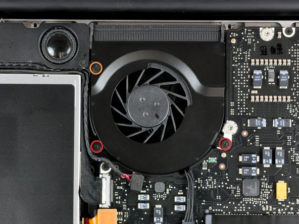
Use a spudger to pry the fan connector straight up off the logic board.
-
-
Questo passaggio è privo di traduzione. Aiuta a tradurlo
-
Remove the following three screws securing the fan to the upper case:
-
Two 5 mm Phillips screws.
-
One 7 mm Phillips screw.
-
-
-
Questo passaggio è privo di traduzione. Aiuta a tradurlo
-
Each connector is different, so the following steps will show you how disconnect each in detail.
-
-
Questo passaggio è privo di traduzione. Aiuta a tradurlo
-
Remove the single Phillips screw securing the battery cable cover to the upper case.
-
Remove the battery cable cover from the upper case.
-
-
Questo passaggio è privo di traduzione. Aiuta a tradurlo
-
Use a spudger to pry the battery level indicator cable connector straight up off the logic board.
-
-
Questo passaggio è privo di traduzione. Aiuta a tradurlo
-
Disconnect the battery cable connector by pulling it straight away from the logic board.
-
-
Questo passaggio è privo di traduzione. Aiuta a tradurlo
-
Using the tip of a spudger, flip up the keyboard ribbon cable retaining flap.
-
Pull the keyboard ribbon cable straight out of its socket.
-
If the smaller connector at the right side of the keyboard ribbon cable is populated by another small black ribbon cable, remove it in a similar way to the above.
-
-
Questo passaggio è privo di traduzione. Aiuta a tradurlo
-
Use the flat end of a spudger to pry the trackpad connector straight up off the logic board.
-
-
Questo passaggio è privo di traduzione. Aiuta a tradurlo
-
Use the tip of a spudger to flip up the locking lever to release the IR sensor ribbon cable from its socket.
-
Use the tip of a spudger to pull the IR sensor ribbon cable straight away from the logic board.
-
-
Questo passaggio è privo di traduzione. Aiuta a tradurlo
-
Use the flat end of a spudger to pry the hard drive cable connector straight up off the logic board.
-
-
Questo passaggio è privo di traduzione. Aiuta a tradurlo
-
Use the flat end of a spudger to pry the optical drive cable connector straight up off the logic board.
-
-
Questo passaggio è privo di traduzione. Aiuta a tradurlo
-
Disconnect the display data cable by pulling the male end straight away from its socket.
-
-
Questo passaggio è privo di traduzione. Aiuta a tradurlo
-
Use the flat end of a spudger to pry the subwoofer cable connector straight up off the logic board.
-
-
Questo passaggio è privo di traduzione. Aiuta a tradurlo
-
Grab the plastic pull tab secured to the display data cable lock and rotate it toward the DC-in side of the computer.
-
Pull the display data cable connector straight away from its socket.
-
-
Questo passaggio è privo di traduzione. Aiuta a tradurlo
-
Remove the following two screws securing the display data cable bracket to the upper case:
-
One 7mm Phillips screw.
-
One 5mm Phillips screw.
-
Remove the two 7 mm Phillips screws from the DC-in board.
-
Lift the display data cable bracket out of the upper case.
-
-
Questo passaggio è privo di traduzione. Aiuta a tradurlo
-
If present, remove the two 4mm Phillips screws securing the bottom case clip to the upper case.
-
Lift the bottom case clip out of the upper case.
-
-
Questo passaggio è privo di traduzione. Aiuta a tradurlo
-
Remove the two 5mm Phillips screws securing the keyboard flex bracket to the upper case.
-
Lift the keyboard flex bracket out of the upper case.
-
-
Questo passaggio è privo di traduzione. Aiuta a tradurlo
-
Use the tip of a spudger to release the microphone from the upper case.
-
-
Questo passaggio è privo di traduzione. Aiuta a tradurlo
-
Remove the following five screws securing the logic board to the upper case:
-
Four 3mm Phillips screws.
-
One 3.5mm Phillips screw.
-
Lift the logic board from its left edge and pull it out of the upper case.
-
-
Questo passaggio è privo di traduzione. Aiuta a tradurlo
-
Disconnect the DC-In Board connector from the logic board by pulling it straight away from its socket.
-


Annulla: non ho completato questa guida.
Altre 48 persone hanno completato questa guida.
