Questa versione può contenere modifiche errate. Passa all'ultima istantanea verificata.
Cosa ti serve
-
-
Con il case chiuso, posizionare l'Unibody capovolto su una superficie piatta.
-
Premere il lato scanalato della chiusura di sgancio dello sportello di accesso, affinché sia possibile prendere l'estremità libera con le mani. Sollevare la chiusura di sgancio finché non è in posizione verticale.
-
-
-
Prendere la linguetta di plastica bianca ed estrarre la batteria, rimuovendola dall'Unibody.
-
-
-
Rimuovere le otto viti seguenti, che fissano il case inferiore al case:
-
Una vite con testa a croce da 3 mm.
-
Tre viti con testa a croce da 13,5 mm.
-
Quattro viti con testa a croce da 3,5 mm.
-
-
Questo passaggio è privo di traduzione. Aiuta a tradurlo
-
Disconnect the camera cable by pulling the male end straight away from its socket.
-
-
Questo passaggio è privo di traduzione. Aiuta a tradurlo
-
De-route the camera data cable from the channel in the optical drive.
-
-
Questo passaggio è privo di traduzione. Aiuta a tradurlo
-
Remove the following screws securing the camera data cable and right speaker to the upper case:
-
One 9.9 mm partially threaded Phillips screw
-
One 9.6 mm threaded Phillips screw
-
One 4 mm Phillips screw
-
Slide the camera cable bracket out from under the subwoofer and remove it from the computer.
-
-
Questo passaggio è privo di traduzione. Aiuta a tradurlo
-
Grab the plastic pull tab secured to the display data cable lock and rotate it toward the DC-in side of the computer.
-
Pull the display data cable connector straight away from its socket.
-
-
Questo passaggio è privo di traduzione. Aiuta a tradurlo
-
Remove the following two screws from the display data cable bracket:
-
One 7 mm Phillips screw.
-
One 5 mm Phillips screw.
-
Lift the display data cable bracket out of the upper case.
-
-
-
Questo passaggio è privo di traduzione. Aiuta a tradurlo
-
Remove the two outer 6 mm Torx screws securing each side of the display to the upper case (4 screws total).
-
-
Questo passaggio è privo di traduzione. Aiuta a tradurlo
-
Open your MacBook so the display is perpendicular to the upper case.
-
Place your opened MacBook on a table as pictured.
-
While holding the display and upper case together with your left hand, remove the 6 mm Torx screw from the lower display bracket.
-
-
Questo passaggio è privo di traduzione. Aiuta a tradurlo
-
Remove the last remaining 6 mm Torx screw securing the display to the upper case.
-
-
Questo passaggio è privo di traduzione. Aiuta a tradurlo
-
Grab the upper case with your right hand and rotate it slightly toward the top of the display so the upper display bracket clears the edge of the upper case.
-
Rotate the display slightly away from the upper case.
-
Lift the display away from the upper case, minding any brackets or cables that may get caught.
-
-
Questo passaggio è privo di traduzione. Aiuta a tradurlo
-
With the heat gun set to low, start by heating the outer black border near the upper right corner of the glass panel.
-
-
Questo passaggio è privo di traduzione. Aiuta a tradurlo
-
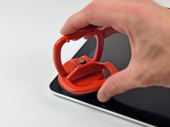
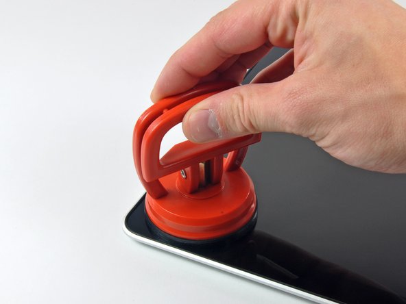
With the panel sufficiently heated, fasten a heavy-duty suction cup near the upper right corner of the display glass.
-
Slowly and gently pull the corner of the display glass up off the display assembly.
-
-
Questo passaggio è privo di traduzione. Aiuta a tradurlo
-
Gently lift the corner of the display glass enough to insert a spudger between it and the display assembly.
-
Use the flat end of a spudger to gently pry up the adhesive securing the front glass to the display.
-
Pry up the glass panel a few inches away from the upper right corner along the top and right edges of the display.
-
-
Questo passaggio è privo di traduzione. Aiuta a tradurlo
-
Use a heat gun to soften the adhesive under the black strip along the right side of the front glass panel.
-
Attach a suction cup along the right side of the front glass panel.
-
Pull up on the glass panel while you use the flat end of a spudger to separate it from the rest of the display assembly.
-
Continue working along the right edge of the front display glass until it is separated from the display.
-
-
Questo passaggio è privo di traduzione. Aiuta a tradurlo
-
Use your heat gun to soften the adhesive under the black strip along the top edge of the glass display panel.
-
Attach a suction cup near the top edge of the glass display panel and use it to pull the glass panel up off the display.
-
Work along the top edge of the glass panel, carefully using the flat end of a spudger to separate the adhesive if necessary.
-
-
Questo passaggio è privo di traduzione. Aiuta a tradurlo
-
Use a heat gun to soften the adhesive under the black strip near the upper left corner of the glass display panel.
-
Attach a suction cup near the upper left corner of the glass display panel.
-
Pull up on the suction cup and use the flat end of a spudger to carefully pry the glass display panel out of the display assembly.
-
-
Questo passaggio è privo di traduzione. Aiuta a tradurlo
-
Use a heat gun to soften the adhesive under the black strip along the left side of the front glass panel.
-
Attach a suction cup along the left side of the front glass panel.
-
Pull up on the glass panel while you use the flat end of a spudger to separate it from the rest of the display assembly.
-
Continue working along the left edge of the front display glass until it is separated from the display.
-
-
Questo passaggio è privo di traduzione. Aiuta a tradurlo
-
Now that the top, left, and right edges of the glass are free from the display, slowly lift the top edge of the glass panel and gently rotate it out of the display.
-
If necessary, use the flat end of a spudger to free the bottom edge of the glass display panel from the display assembly.
-
-
Questo passaggio è privo di traduzione. Aiuta a tradurlo
-
Insert the edge of a plastic opening tool between the display glass and the camera bracket, and run it around the camera bracket to separate it from the display glass.
-
-
Questo passaggio è privo di traduzione. Aiuta a tradurlo
-
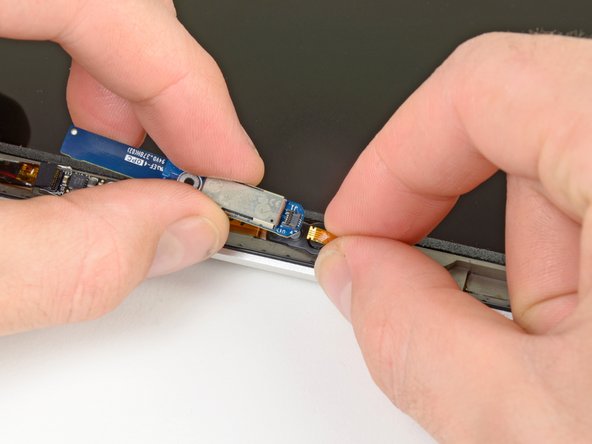
To reconnect the cable, first use the tip of a spudger to remove the piece of foam tape over the AirPort & iSight data cable ZIF socket.
-
Use the tip of a spudger to flip up the ZIF cable retainer on the AirPort & iSight data cable socket.
-
Insert the AirPort & iSight data cable into its socket on the camera board and use the tip of a spudger to snap down the ZIF cable retainer, locking the cable in place.
-
-
Questo passaggio è privo di traduzione. Aiuta a tradurlo
-
Remove the single 3 mm Phillips #00 screw securing the Bluetooth board to the display assembly.
-
-
Questo passaggio è privo di traduzione. Aiuta a tradurlo
-
Use the flat end of spudger to flip up the Bluetooth board from its recess within the display assembly.
-
-
Questo passaggio è privo di traduzione. Aiuta a tradurlo
-
Lift and bend the Bluetooth board towards the left hand side of the display assembly.
-
-
Questo passaggio è privo di traduzione. Aiuta a tradurlo
-
Use the tip of a spudger or your fingernail to flip up the retaining flap on the Bluetooth board ribbon cable ZIF socket.
-
Pull the Bluetooth board ribbon cable out of its socket.
-
Lift and remove the Bluetooth board from the display assembly.
-


Annulla: non ho completato questa guida.
Altre 3 persone hanno completato questa guida.
