Questa versione può contenere modifiche errate. Passa all'ultima istantanea verificata.
Cosa ti serve
-
-
Svita le seguenti viti che fissano la scocca inferiore a quella superiore:
-
Tre viti a croce Phillips da 13,5 mm.
-
Sette viti a croce Phillips da 3 mm.
-
-
-
Se presente, afferra la linguetta di plastica attaccata al connettore della batteria e tirala verso il lato anteriore del dispositivo. Per i modelli di fine 2011, il connettore non avrà una linguetta ed è semplicemente una spina che si inserisce direttamente nella scheda madre, per rimuoverla tirala verso l'alto.
-
-
Questo passaggio è privo di traduzione. Aiuta a tradurlo
-
Use the tip of a spudger to push the small plastic cable retainer away from the camera cable socket for enough clearance to remove the camera cable.
-
-
Questo passaggio è privo di traduzione. Aiuta a tradurlo
-
Pull the camera cable toward the optical drive opening to disconnect it from the logic board.
-
-
Questo passaggio è privo di traduzione. Aiuta a tradurlo
-
Carefully pull the Bluetooth cable toward the fans to disconnect it from the Bluetooth board.
-
-
Questo passaggio è privo di traduzione. Aiuta a tradurlo
-
Use the flat end of a spudger to peel the thin plastic cover off the top and sides of the Bluetooth board housing. For late-2011 models check out the other picture because the connector location is in a totally different location.
-
-
-
Questo passaggio è privo di traduzione. Aiuta a tradurlo
-
Use the flat end of a spudger to pry the Bluetooth antenna connector up and off its socket on the Bluetooth board.
-
-
Questo passaggio è privo di traduzione. Aiuta a tradurlo
-
De-route the camera cable from the slot molded into the Bluetooth board housing.
-
-
Questo passaggio è privo di traduzione. Aiuta a tradurlo
-
Remove the two 7.1 mm Phillips screws securing the camera cable retainer to the upper case.
-
Remove the camera cable retainer from the upper case.
-
-
Questo passaggio è privo di traduzione. Aiuta a tradurlo
-
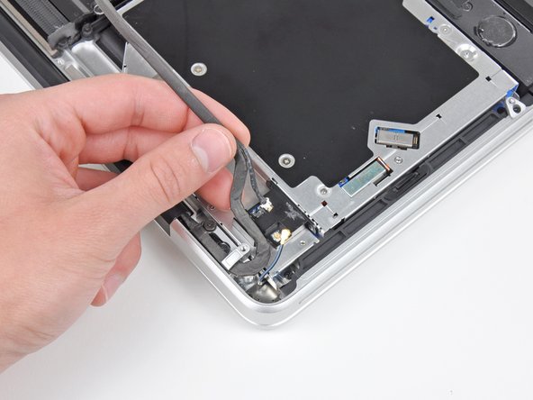
Lift the black plastic flap attached to the display data cable retainer and rotate it toward the DC-In side of the MacBook.
-
Pull the display data cable out of its socket.
-
-
Questo passaggio è privo di traduzione. Aiuta a tradurlo
-
Remove the two 7.1 mm Phillips screws securing the display data cable retainer to the upper case.
-
Remove the display data cable retainer.
-
-
Questo passaggio è privo di traduzione. Aiuta a tradurlo
-
Remove the two outer 6.8 mm T6 Torx screws from each of the two display brackets (four screws total).
-
-
Questo passaggio è privo di traduzione. Aiuta a tradurlo
-
While holding the display and upper case together with your left hand, remove the remaining T6 Torx screw from the lower display bracket.
-
-
Questo passaggio è privo di traduzione. Aiuta a tradurlo
-
Remove the last remaining T6 Torx screw securing the display to the upper case.
-
-
Questo passaggio è privo di traduzione. Aiuta a tradurlo
-
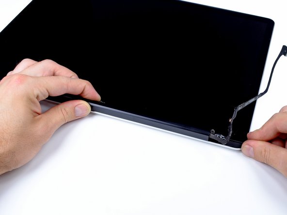
Grab the upper case with your right hand and rotate it slightly toward the top of the display so the upper display bracket clears the edge of the upper case.
-
Rotate the display slightly away from the upper case.
-
Lift the display up and away from the upper case, minding any brackets or cables that may get caught.
-
-
Questo passaggio è privo di traduzione. Aiuta a tradurlo
-
Grab the clutch cover as shown and slide it toward the right side of the display.
-
-
Questo passaggio è privo di traduzione. Aiuta a tradurlo
-
Lifting the left edge of the clutch cover, gently rock it back and forth on its long axis while pulling it away from the display.
-
Remove the clutch cover from the display, minding any cables that may get caught.
-
-
Questo passaggio è privo di traduzione. Aiuta a tradurlo
-
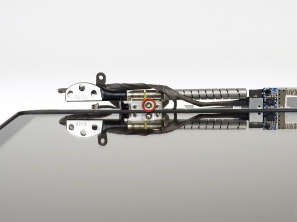
Remove the three 5.2 mm T6 Torx screws securing the right clutch hinge to the display assembly.
-
-
Questo passaggio è privo di traduzione. Aiuta a tradurlo
-
Remove the right cltuch hinge from the display assembly.
-
Remove the plastic hinge guard as well, making sure to not lose it.
-


Annulla: non ho completato questa guida.
Altre 7 persone hanno completato questa guida.

4 Commenti
I had a broken right hinge and replaced it using this guide. The pictures were amazingly spot-on and clearly illustrated the procedure to be followed.
The one thing I did not find (perhaps because Apple Support had previously opened this up to test the hinge) was the "plastic hinge guard" - would be great if you folk could add a pic of this.
The other thing I found a bit hard was the final separation of the display unit and its reattachment which I got through kind of by trial and error. But no biggie. Thanks for this guide - it was MOST helpful!
Hello everyone, does this guide also apply for the 15 inch late 2011 model?
My teardown revealed that the real failure was of the thread locking compound on the screws permitting them to come loose and the hinge to therefore rock, not an internal hinge failure. The new hinges were therefore installed with fresh fastener locking compound. This would be a recommended additional supply for this solution.
Any advice on finding parts? I just picked up an Early 2011, 17-incher and the screen hinges are less than tight, if not "floppy."