Questa versione può contenere modifiche errate. Passa all'ultima istantanea verificata.
Cosa ti serve
-
-
Svita le seguenti viti che fissano la scocca inferiore a quella superiore:
-
Tre viti a croce Phillips da 13,5 mm.
-
Sette viti a croce Phillips da 3 mm.
-
-
-
Se presente, afferra la linguetta di plastica attaccata al connettore della batteria e tirala verso il lato anteriore del dispositivo. Per i modelli di fine 2011, il connettore non avrà una linguetta ed è semplicemente una spina che si inserisce direttamente nella scheda madre, per rimuoverla tirala verso l'alto.
-
-
Questo passaggio è privo di traduzione. Aiuta a tradurlo
-
Use the flat end of a spudger to lift the right fan connector out of its socket on the logic board.
-
-
Questo passaggio è privo di traduzione. Aiuta a tradurlo
-
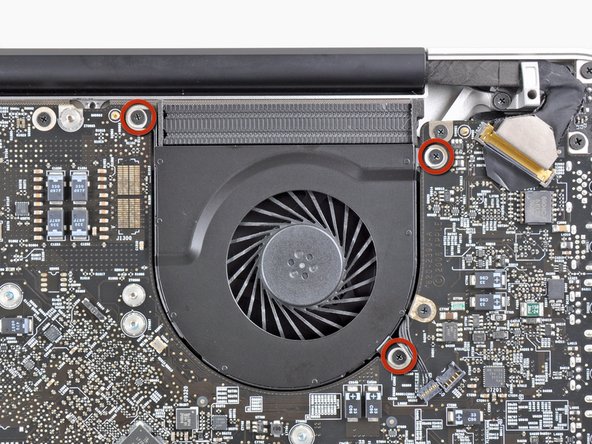
Remove the three 3.1 mm Phillips screws securing the right fan to the logic board.
-
-
Questo passaggio è privo di traduzione. Aiuta a tradurlo
-
Remove the right fan from the upper case, minding its cable that may get caught.
-
-
Questo passaggio è privo di traduzione. Aiuta a tradurlo
-
Use the flat end of a spudger to lift the left fan connector out of its socket on the logic board.
-
-
Questo passaggio è privo di traduzione. Aiuta a tradurlo
-
Remove the three 3.1 mm Phillips screws securing the left fan to the logic board.
-
Remove the left fan from the upper case, minding its cable that may get caught.
-
-
Questo passaggio è privo di traduzione. Aiuta a tradurlo
-
Use the tip of a spudger or your fingernail to flip up the retaining flap on the keyboard backlight ribbon cable.
-
Pull the keyboard backlight ribbon cable out of its socket.
-
-
-
Questo passaggio è privo di traduzione. Aiuta a tradurlo
-
Use the tip of a spudger to push the small plastic cable retainer away from the camera cable socket for enough clearance to remove the camera cable.
-
-
Questo passaggio è privo di traduzione. Aiuta a tradurlo
-
Pull the camera cable toward the optical drive opening to disconnect it from the logic board.
-
-
Questo passaggio è privo di traduzione. Aiuta a tradurlo
-
Use the flat end of a spudger to pry the optical drive connector up and out of its socket on the logic board.
-
-
Questo passaggio è privo di traduzione. Aiuta a tradurlo
-
Use the flat end of a spudger to lift the subwoofer & right speaker connector out of its socket on the logic board.
-
-
Questo passaggio è privo di traduzione. Aiuta a tradurlo
-
Use the tip of a spudger or your fingernail to flip up the retaining flap on the IR sensor ribbon cable socket.
-
Pull the IR sensor ribbon cable out of its socket.
-
-
Questo passaggio è privo di traduzione. Aiuta a tradurlo
-
Remove the following four screws:
-
Two 3.5 mm Phillips screws
-
Two 1.6 mm Phillips screws
-
Remove both connector shields from the logic board.
-
-
Questo passaggio è privo di traduzione. Aiuta a tradurlo
-
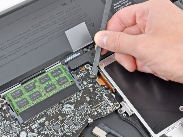
Use the flat end of a spudger to pry the trackpad connector up and out of its socket on the logic board.
-
-
Questo passaggio è privo di traduzione. Aiuta a tradurlo
-
Use your fingernail to flip up the retaining flap on the keyboard ribbon cable socket.
-
Pull the keyboard ribbon cable out of its socket.
-
-
Questo passaggio è privo di traduzione. Aiuta a tradurlo
-
Use your fingernail to flip up the retaining flap on the express card cage ribbon cable socket.
-
Pull the express card cage ribbon cable out of its socket.
-
-
Questo passaggio è privo di traduzione. Aiuta a tradurlo
-
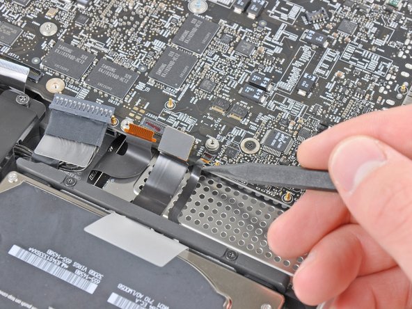
Use the flat end of a spudger to lift the hard drive cable connector up and out of its socket on the logic board.
-
-
Questo passaggio è privo di traduzione. Aiuta a tradurlo
-
Use the tip of a spudger or your fingernail to flip up the retaining flap on the battery indicator cable socket.
-
Pull the battery indicator ribbon cable out of its socket.
-
-
Questo passaggio è privo di traduzione. Aiuta a tradurlo
-
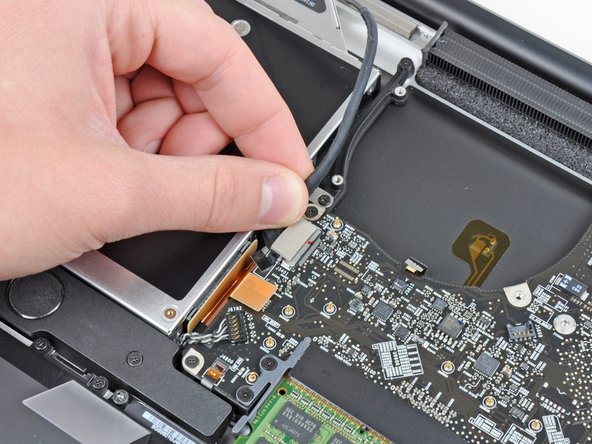
Lift the black plastic flap attached to the display data cable retainer and rotate it toward the DC-In side of the MacBook.
-
Pull the display data cable out of its socket.
-
-
Questo passaggio è privo di traduzione. Aiuta a tradurlo
-
Remove the following eight screws securing the logic board and DC-In board to the upper case:
-
Six 3.2 mm Phillips screws
-
Two 7.6 mm Phillips screws
-
-
Questo passaggio è privo di traduzione. Aiuta a tradurlo
-
Lift the logic board assembly from the side nearest the optical drive and lift it away from the upper case.
-
Carefully pull the ports and DC-In board away from the side of the upper case and remove the logic board assembly, minding any cables that may get caught.
-
-
Questo passaggio è privo di traduzione. Aiuta a tradurlo
-
Remove the two 7.9 mm Phillips screws securing the left speaker assembly to the logic board.
-
-
Questo passaggio è privo di traduzione. Aiuta a tradurlo
-
Slightly lift the left speaker assembly off the logic board.
-
Use the flat end of a spudger to lift the microphone and left speaker connectors out of their sockets on the logic board.
-
Remove the left speaker assembly from the logic board.
-
-
Questo passaggio è privo di traduzione. Aiuta a tradurlo
-
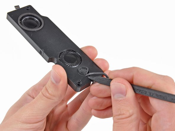
De-route the microphone cable from the channel molded into the left speaker enclosure.
-
Use the tip of a spudger to lift the microphone out of the left speaker enclosure.
-
Microphone remains.
-


Annulla: non ho completato questa guida.
Altre 3 persone hanno completato questa guida.

Un commento
We’re going to have to make some changes here. In Step 10 for Late 2011 models, the camera cable looks different, is located in a different place on the logic board, and detaches differently. Yes, there are 5 comments there, but no pictures.