Questa versione può contenere modifiche errate. Passa all'ultima istantanea verificata.
Cosa ti serve
-
-
Svita le seguenti viti che fissano la scocca inferiore a quella superiore:
-
Tre viti a croce Phillips da 13,5 mm.
-
Sette viti a croce Phillips da 3 mm.
-
-
-
Se presente, afferra la linguetta di plastica attaccata al connettore della batteria e tirala verso il lato anteriore del dispositivo. Per i modelli di fine 2011, il connettore non avrà una linguetta ed è semplicemente una spina che si inserisce direttamente nella scheda madre, per rimuoverla tirala verso l'alto.
-
-
Questo passaggio è privo di traduzione. Aiuta a tradurlo
-
Use the tip of a spudger to push the small plastic cable retainer away from the camera cable socket for enough clearance to remove the camera cable.
-
-
Questo passaggio è privo di traduzione. Aiuta a tradurlo
-
Pull the camera cable toward the optical drive opening to disconnect it from the logic board.
-
-
Questo passaggio è privo di traduzione. Aiuta a tradurlo
-
Carefully pull the Bluetooth cable toward the fans to disconnect it from the Bluetooth board.
-
-
Questo passaggio è privo di traduzione. Aiuta a tradurlo
-
Use the flat end of a spudger to peel the thin plastic cover off the top and sides of the Bluetooth board housing. For late-2011 models check out the other picture because the connector location is in a totally different location.
-
-
Questo passaggio è privo di traduzione. Aiuta a tradurlo
-
Use the flat end of a spudger to pry the Bluetooth antenna connector up and off its socket on the Bluetooth board.
-
-
Questo passaggio è privo di traduzione. Aiuta a tradurlo
-
De-route the camera cable from the slot molded into the Bluetooth board housing.
-
-
Questo passaggio è privo di traduzione. Aiuta a tradurlo
-
Remove the two 7.1 mm Phillips screws securing the camera cable retainer to the upper case.
-
Remove the camera cable retainer from the upper case.
-
-
Questo passaggio è privo di traduzione. Aiuta a tradurlo
-
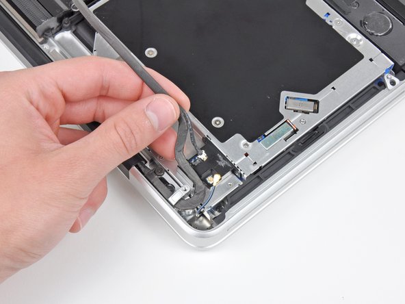
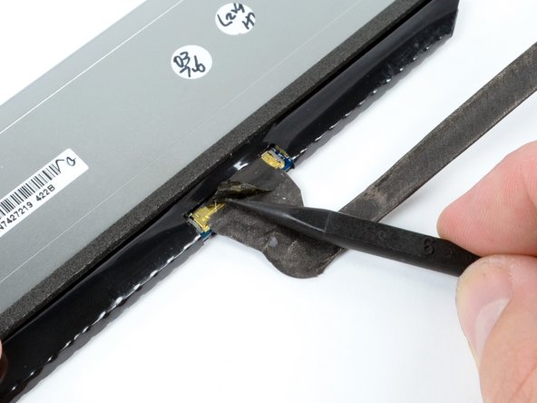
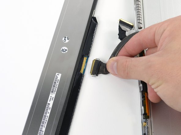
Lift the black plastic flap attached to the display data cable retainer and rotate it toward the DC-In side of the MacBook.
-
Pull the display data cable out of its socket.
-
-
Questo passaggio è privo di traduzione. Aiuta a tradurlo
-
Remove the two 7.1 mm Phillips screws securing the display data cable retainer to the upper case.
-
Remove the display data cable retainer.
-
-
-
Questo passaggio è privo di traduzione. Aiuta a tradurlo
-
Remove the two outer 6.8 mm T6 Torx screws from each of the two display brackets (four screws total).
-
-
Questo passaggio è privo di traduzione. Aiuta a tradurlo
-
While holding the display and upper case together with your left hand, remove the remaining T6 Torx screw from the lower display bracket.
-
-
Questo passaggio è privo di traduzione. Aiuta a tradurlo
-
Remove the last remaining T6 Torx screw securing the display to the upper case.
-
-
Questo passaggio è privo di traduzione. Aiuta a tradurlo
-
Grab the upper case with your right hand and rotate it slightly toward the top of the display so the upper display bracket clears the edge of the upper case.
-
Rotate the display slightly away from the upper case.
-
Lift the display up and away from the upper case, minding any brackets or cables that may get caught.
-
-
Questo passaggio è privo di traduzione. Aiuta a tradurlo
-
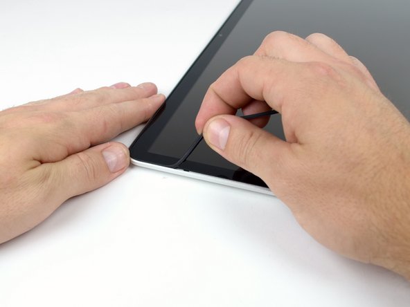
Insert a plastic opening tool underneath the black rubber gasket at the bottom left corner of the display assembly.
-
Gently pry the wide edge of the gasket up from the back case.
-
-
Questo passaggio è privo di traduzione. Aiuta a tradurlo
-
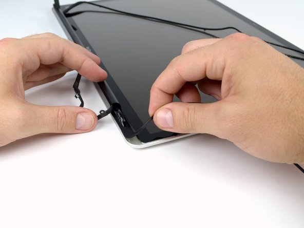
Starting with the freed corner, pull the left gasket off the left side of the display assembly.
-
-
Questo passaggio è privo di traduzione. Aiuta a tradurlo
-
Continue pulling the display gasket off the display assembly across the top edge.
-
-
Questo passaggio è privo di traduzione. Aiuta a tradurlo
-
Continue pulling the display gasket off the display assembly down the right side.
-
Pull the gasket off the bottom edge of the display to completely free it and set it aside.
-
-
Questo passaggio è privo di traduzione. Aiuta a tradurlo
-
Before starting, be sure to clean the display glass with a lint-free cloth moistened with a mild solution; it will make the suction cup adhere better, and will make checking for dust on reassembly easier.
-
With the heat gun set to low, start by heating the outer black border near the upper right corner of the glass panel.
-
-
Questo passaggio è privo di traduzione. Aiuta a tradurlo
-
With the panel sufficiently heated, fasten a heavy-duty suction cup near the lower right corner of the display glass.
-
To attach the suction cups we sell, first position the suction cup with the movable handle parallel to the face of the glass panel. While lightly holding the suction cup against the glass, raise the movable handle until it is parallel with the other handle.
-
Gently lift the corner of the display glass enough to insert a guitar pick between it and the display assembly.
-
Use the guitar pick to gently pry up the adhesive securing the front glass to the display.
-
Pry up the glass panel along the right edge of the display up to the halfway point.
-
Leave the guitar pick in place halfway up the right side of the display and remove the suction cup.
-
-
Questo passaggio è privo di traduzione. Aiuta a tradurlo
-
Use a heat gun to soften the adhesive under the display glass along the right and top edges of the display.
-
Attach a suction cup to the upper right corner of the front glass panel.
-
Pull up on the glass panel while you use a second guitar pick to separate it from the rest of the display assembly.
-
Continue working along the right edge of the front display glass until it is separated from the display.
-
-
Questo passaggio è privo di traduzione. Aiuta a tradurlo
-
Work along the top edge of the display assembly, carefully prying the adhesive up with the guitar pick.
-
Stop prying about an inch before you reach the iSight camera. Leave the guitar pick in place and remove the suction cup.
-
-
Questo passaggio è privo di traduzione. Aiuta a tradurlo
-
Repeat steps 22 through 24 for the left side and the left top edge of the display.
-
-
Questo passaggio è privo di traduzione. Aiuta a tradurlo
-
After prying up the three edges of the display glass, you should have four guitar picks resting underneath the panel, as shown.
-
-
Questo passaggio è privo di traduzione. Aiuta a tradurlo
-
With the heat gun set to low, heat the bottom edge of the display to soften the adhesive holding the glass in place.
-
Slowly lift the top edge of the glass panel and gently rotate it out of the display.
-
-
Questo passaggio è privo di traduzione. Aiuta a tradurlo
-
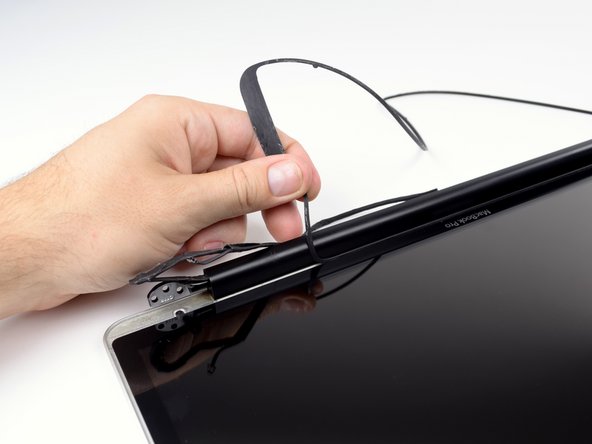
Holding the clutch cover firmly, slide it towards the right display hinge.
-
-
Questo passaggio è privo di traduzione. Aiuta a tradurlo
-
Lifting the left edge of the clutch cover, gently rock it back and forth on its long axis while pulling it away from the display.
-
Remove the clutch cover from the display, minding any cables that may get caught.
-
-
Questo passaggio è privo di traduzione. Aiuta a tradurlo
-
Remove the four 2.3 mm Phillips #00 screws securing the LCD to the rear display bezel.
-
-
Questo passaggio è privo di traduzione. Aiuta a tradurlo
-
Lift one of the top corners of the LCD panel out of the rear bezel with a plastic opening tool.
-
Grasp the top corners of the LCD and rotate it upwards, slightly out of the display.
-
Pull the LCD toward the top of the display panel, freeing the screw tabs from underneath the rear display bezel.
-
-
Questo passaggio è privo di traduzione. Aiuta a tradurlo
-
Carefully guide the LCD cable through the slot in the rear display bezel.
-
-
Questo passaggio è privo di traduzione. Aiuta a tradurlo
-
Flip the LCD over and lay it face down, being careful to not put too much stress on the display cable.
-
Peel the piece of tape covering the display data cable connector away from the edge closest to the LCD.
-
-
Questo passaggio è privo di traduzione. Aiuta a tradurlo
-
Use the tip of a spudger to flip up the thin steel retaining clip securing the display data cable to its socket on the LCD.
-
Pull the display data cable straight away from its socket on the LCD.
-
Lift the LCD out of the display assembly and set it aside.
-


Annulla: non ho completato questa guida.
Altre 32 persone hanno completato questa guida.


8 Commenti
As much a question as a comment. I have the antiglare version of this MBP which has a 10mm aluminium surround on the screen (it isn't listed on the MBP page) so this guide only applies, as far as I can tell, up to step 16.
As I'm not sure how things progress from there on, I think I'll not venture so far.
There is a guide for the 15" MacBook Pro that illustrates replacing the matte screen. In fact, you can pretty much follow that guide all the way through for the 17" as well. There are a few differences but not enough to trip you up.
Replacing the screen, the only trouble I encountered was with the front bezel. Be EXTRA careful when removing the bezel so that you don't warp/bend/crease it in any manner. Use generous amounts of heat and take the extra time. If the bezel does become out of shape, it will be difficult to glue it back on to the lid.
Hope that helps.
nunchukS -
April 30, 2016 - My Mid-2010 17" Macbook Pro Unibody (A1297) 6,2 did not look like the pictures shown in this guide. Starting at the step where the Bluetooth Cable is removed.
Where can I get a version of this LCD Replacement that matches my laptop? What other info is needed to determine?
Thanks,
Bill Fulbright