Questa versione può contenere modifiche errate. Passa all'ultima istantanea verificata.
Cosa ti serve
-
-
Rimuovi le dieci viti seguenti, che fissano il case inferiore a quello superiore:
-
Tre viti con testa a croce Phillips da 13,5 (14,1) mm.
-
Sette viti con testa a croce da 3 mm.
-
-
-
Usa l'estremità di uno spudger per rimuovere il connettore della batteria dal suo zoccolo sulla scheda logica.
-
-
Questo passaggio è privo di traduzione. Aiuta a tradurlo
-
Remove the following three screws securing the left fan to the logic board:
-
Two 3.5 mm T6 Torx screws.
-
One 4.2 mm T6 Torx screw.
-
-
Questo passaggio è privo di traduzione. Aiuta a tradurlo
-
Use the flat end of a spudger to disconnect the left fan connector from the logic board.
-
-
-
Usa la parte piatta di uno spudger per scollegare il connettore della ventola destra dalla sua presa sulla scheda madre.
-
-
-
-
Solleva attentamente il gruppo della scheda madre dal suo bordo sinistro per rimuoverla dal case superiore, stando attento al cavo del lettore CD e le porte I/O che possono impigliarsi durante la rimozione.
-
Se necessario, usa la parte piatta di uno spudger per separare il microfono dal case superiore.
-
Tira via il lato delle porte I/O dal bordo del case superiore e rimuovi il gruppo della scheda madre.
-
-
Questo passaggio è privo di traduzione. Aiuta a tradurlo
-
Remove the two 7.5 mm ( 7.2 mm )Tri-point screws securing the battery to the upper case.
-
-
Questo passaggio è privo di traduzione. Aiuta a tradurlo
-
Carefully peel the battery warning label off the upper case between the battery and the optical drive to reveal an additional Tri-point screw.
-
Remove the last 7.5 mm ( 7.2 mm ) Tri-point screw securing the battery to the upper case.
-
-
Questo passaggio è privo di traduzione. Aiuta a tradurlo
-
Use the attached plastic pull tab to remove the battery from the upper case.
-
-
Questo passaggio è privo di traduzione. Aiuta a tradurlo
-
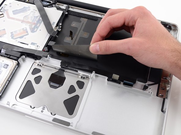
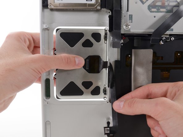
Use the flat end of a spudger to peel up the edge of the large piece of black tape covering the trackpad cable.
-
Peel the tape up and fold it back out of the way of the trackpad cable. Leaving it in place on the upper case will make it easier to reapply it during reassembly.
-
-
Questo passaggio è privo di traduzione. Aiuta a tradurlo
-
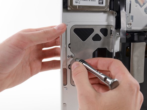
Remove the four silver 1.3 mm Phillips #00 screws from the trackpad spring brackets.
-
-
Questo passaggio è privo di traduzione. Aiuta a tradurlo
-
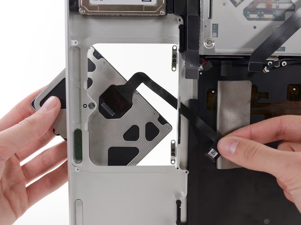
Once the trackpad is free of the upper case, guide the ribbon cable through the slot cut in the upper case.
-
-
Questo passaggio è privo di traduzione. Aiuta a tradurlo
-
When reinstalling the trackpad, loosely replace the four Phillips screws and check the alignment of the trackpad on the keyboard side of the upper case.
-
Once you have centered the trackpad in the upper case, tighten the Phillips screws all the way.
-
Use the large Tri-point screw at the bottom of the trackpad to adjust the click stroke.
-


Annulla: non ho completato questa guida.
Altre 57 persone hanno completato questa guida.

14 Commenti
Be extremely careful about the keyboard backlight socket. I ended up breaking off an infinitesimally small side of the plastic socket and I have no keyboard backlight now. This doesn't bother me that much, but still irritating!
Dang - I did the same thing. Thankfully it was on the questionable logic board in the machine I was scavenging the “good” trackpad from, so I didn’t do the same to the good one. Overall, a very good set of instructions - thank you to the author.
Dave M -
Very easy process, one observation is that the holes which the screws that hold the battery in shattered, they're very brittle, had to hot glue my battery back in, double sided tape would have been better. Hardest part was the alignment of the new trackpad, but if you take your time to align it and use sellotape to hold it in place while you flip the MacBook and tighten it, everything will be all good.
Many thanks to the author
+ It is important to make sure you connected well the keyboard/trackpad cable
+ Test if your keyboard is working before attempting to reset either the PRAM/NVRAM and the System Management Controller (SMC), which, although not required, I would recommend doing after replacing a piece of hardware like the trackpad
+ Thanks for these instructions
Well, thanks for the good instructions…But (IMHO) if you only need to replace the trackpad and not the trackpad ribbon cable it is NOT necessary to follow all these steps, E.g. you do not have to remove logic board and all, just follow steps to remove battery, unscrew the trackpad, carefully remove cable on the trackpad side (the cable has also a connector there) and done. Then vice versa Maybe 20 minutes work.