Questa versione può contenere modifiche errate. Passa all'ultima istantanea verificata.
Cosa ti serve
-
-
Rimuovi le dieci viti seguenti, che fissano il case inferiore a quello superiore:
-
Tre viti con testa a croce Phillips da 13,5 (14,1) mm.
-
Sette viti con testa a croce da 3 mm.
-
-
-
Usa l'estremità di uno spudger per rimuovere il connettore della batteria dal suo zoccolo sulla scheda logica.
-
-
Questo passaggio è privo di traduzione. Aiuta a tradurlo
-
Pull the camera cable connector straight out of its socket on the logic board.
-
-
-
Questo passaggio è privo di traduzione. Aiuta a tradurlo
-
Use the flat end of a spudger to carefully pry the AirPort/Bluetooth ribbon cable up off its socket on the logic board.
-
-
Questo passaggio è privo di traduzione. Aiuta a tradurlo
-
Use the tip of a spudger to pry the four antenna connectors up from their sockets on the AirPort/Bluetooth board.
-
-
Questo passaggio è privo di traduzione. Aiuta a tradurlo
-
De-route all four antenna cables from their channels in the AirPort/Bluetooth housing.
-
De-route the camera cable from its channel in the AirPort/Bluetooth housing.
-
-
Questo passaggio è privo di traduzione. Aiuta a tradurlo
-
Remove the following two screws securing the AirPort/Bluetooth assembly to the upper case:
-
One 8.6 mm Phillips screw
-
One 3.9 mm Phillips screw
-
-
Questo passaggio è privo di traduzione. Aiuta a tradurlo
-
Remove the AirPort/Bluetooth assembly from the upper case, minding any cables that may get caught.
-
-
Questo passaggio è privo di traduzione. Aiuta a tradurlo
-
Peel and remove the piece of EMI tape wrapped around the AirPort/Bluetooth assembly.
-
-
Questo passaggio è privo di traduzione. Aiuta a tradurlo
-
Use the flat end of a spudger to pry the AirPort/Bluetooth cable away from its socket on the AirPort/Bluetooth board.
-
Remove the AirPort/Bluetooth cable from the AirPort/Bluetooth assembly.
-
-
Questo passaggio è privo di traduzione. Aiuta a tradurlo
-
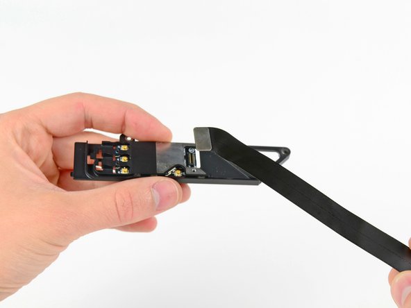
Remove the three Phillips screws securing the AirPort/Bluetooth board to the AirPort/Bluetooth board housing.
-
Use the flat end of a spudger to dislodge the AirPort/Bluetooth board from its recess in the AirPort/Bluetooth board housing.
-
-
Questo passaggio è privo di traduzione. Aiuta a tradurlo
-
Remove the AirPort/Bluetooth board from its aluminum housing.
-


Annulla: non ho completato questa guida.
Altre 32 persone hanno completato questa guida.

6 Commenti
I'm interested to replace the Airpot/Bluetooth Board on my MPB Late 2011 (MacbookPro 8,2) that currently has the board BCM 2070B0. I need to be sure that the replacement board at this link (http://www.ebay.com/itm/Macbook-Pro-A127...) will fit with my MBP.
The next question is related to the replacement of the aluminium frame as well as mentioned at the beginning of this article or is the current one is ok as well. I have available the images of the HW data of my MBP if need to properly answer the questions.
Many thanks for your great help.
Best regards
Paolo
Used this to replace my late 2011 Airport/Bluetooth board with a slightly later one that fits the same and enabled Bluetooth 4.0. BCM94331PCIEBT4AX => BCM94331PCIEBT4ACX.
Do you mind if I ask which Bluetooth board you updated to and where you bought it?
Colin -
hello i have a MacBookPro 6.2. Midle 2010
i’m also interested to replace the Airpot/Bluetooth Board for a higher Version. ?!
is there a option, an with witch Card.