Questa versione può contenere modifiche errate. Passa all'ultima istantanea verificata.
Cosa ti serve
-
-
Con il case chiuso, posizionare l'Unibody capovolto su una superficie piatta.
-
Premere il lato scanalato della chiusura di sgancio dello sportello di accesso, affinché sia possibile prendere l'estremità libera con le mani. Sollevare la chiusura di sgancio finché non è in posizione verticale.
-
-
-
Afferra la linguetta di plastica trasparente e tira la batteria verso l'alto per rimuoverla dall'Unibody.
-
Premendo la chiusura, questa bloccherà la batteria in posizione.
-
-
-
Rimuovere le otto viti seguenti, che fissano il case inferiore al case:
-
Una vite con testa a croce da 5,4 mm.
-
Tre viti con testa a croce da 14 mm.
-
Quattro viti con testa a croce da 3,5 mm.
-
-
Questo passaggio è privo di traduzione. Aiuta a tradurlo
-
Remove the following 5 screws securing the mid wall to the upper case:
-
Three 10.5 mm Phillips screws.
-
Two 3.7 mm Phillips screws.
-
-
Questo passaggio è privo di traduzione. Aiuta a tradurlo
-
Remove the following six screws securing both the right fan and the left fan to the logic board:
-
Four 3.5 mm Phillips screws.
-
Two 3.2 mm Phillips screws.
-
-
Questo passaggio è privo di traduzione. Aiuta a tradurlo
-
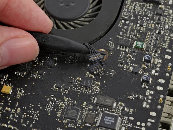
Use the tip of a spudger to lift the right fan connector straight up from its socket on the logic board.
-
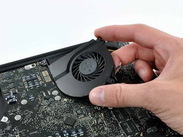
Remove the right fan from the case.
-
-
Questo passaggio è privo di traduzione. Aiuta a tradurlo
-
Use the tip of a spudger to lift the left fan connector straight up from its socket on the logic board.
-
Remove the left fan from the case.
-
-
-
Questo passaggio è privo di traduzione. Aiuta a tradurlo
-
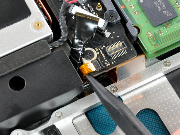
Remove any adhesive from the camera cable connector.
-
Disconnect the camera cable by pulling the male end out of its socket, parallel to the logic board, do not lift it upwards.
-
-
Questo passaggio è privo di traduzione. Aiuta a tradurlo
-
Use a spudger to carefully pry the optical drive connector straight up off its socket on the logic board.
-
-
Questo passaggio è privo di traduzione. Aiuta a tradurlo
-
Using the flat end of a spudger, pry the subwoofer connector straight up off its socket on the logic board.
-
-
Questo passaggio è privo di traduzione. Aiuta a tradurlo
-
Use the flat end of a spudger to pry the silver-colored hard drive cable connector straight up out of its socket on the logic board.
-
-
Questo passaggio è privo di traduzione. Aiuta a tradurlo
-
Use a spudger to pry the trackpad connector straight up out of its socket on the logic board.
-
-
Questo passaggio è privo di traduzione. Aiuta a tradurlo
-
Using the tip of a spudger, flip up the IR/sleep LED ribbon cable retaining flap.
-
Pull the IR/sleep LED ribbon cable straight out of its socket.
-
-
Questo passaggio è privo di traduzione. Aiuta a tradurlo
-
Use a spudger to pry the battery indicator light connector straight up out of its socket on the logic board.
-
-
Questo passaggio è privo di traduzione. Aiuta a tradurlo
-
Using the tip of a spudger, flip up the keyboard ribbon cable retaining flap.
-
Pull the keyboard ribbon cable straight out of its socket.
-
-
Questo passaggio è privo di traduzione. Aiuta a tradurlo
-
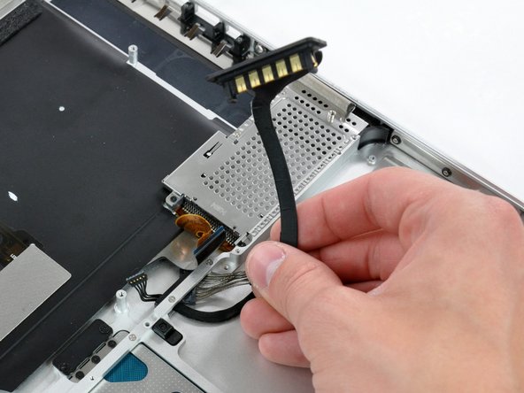
Using the tip of a spudger, flip up the express card cage ribbon cable retaining flap.
-
Pull the express card cage ribbon cable straight out of its socket.
-
-
Questo passaggio è privo di traduzione. Aiuta a tradurlo
-
Using the flat end of a spudger, pry the microphone cable connector straight up out of its socket on the logic board.
-
-
Questo passaggio è privo di traduzione. Aiuta a tradurlo
-
Grab the plastic pull tab secured to the display data cable lock and rotate it toward the DC-in side of the computer.
-
Pull the display data cable connector straight away from its socket.
-
-
Questo passaggio è privo di traduzione. Aiuta a tradurlo
-
Locate the keyboard backlight ribbon cable (near the left fan space).
-
Using the tip of a spudger, flip up the keyboard backlight ribbon cable retaining flap.
-
Pull the keyboard backlight ribbon cable straight out of its socket.
-
-
Questo passaggio è privo di traduzione. Aiuta a tradurlo
-
Remove seven 3.2 mm Phillips screws securing the logic board to the upper case.
-
-
Questo passaggio è privo di traduzione. Aiuta a tradurlo
-
Remove two 7 mm Phillips screws securing the DC-in board to the upper case.
-
-
Questo passaggio è privo di traduzione. Aiuta a tradurlo
-
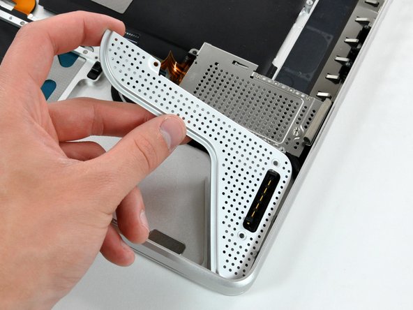
Remove two 3.5 mm Phillips screws securing the bottom case clip to the upper case.
-
Lift the bottom case clip out of the upper case.
-
-
Questo passaggio è privo di traduzione. Aiuta a tradurlo
-
Carefully lift the logic board assembly from the left side and work it out of the upper case, minding the port side that may get caught during removal.
-
-
Questo passaggio è privo di traduzione. Aiuta a tradurlo
-
Lift the logic board enough to grab the battery connector and pull it straight away from its socket on the logic board.
-
Lift the logic board assembly out of the upper case.
-
-
Questo passaggio è privo di traduzione. Aiuta a tradurlo
-
Remove three 2 mm Phillips screws securing the battery connector cover to the upper case.
-
-
Questo passaggio è privo di traduzione. Aiuta a tradurlo
-
Lift the battery connector cover out of the upper case.
-
-
Questo passaggio è privo di traduzione. Aiuta a tradurlo
-
Peel the battery connector cable off the adhesive securing it to the upper case.
-
De-route the battery connector cable through the gap in the upper case and remove it from the computer.
-


Annulla: non ho completato questa guida.
Altre 8 persone hanno completato questa guida.

Un commento
can anyone tell me where i can buy a battery connector for this mbp model? cannot find it anywhere?