Questa versione può contenere modifiche errate. Passa all'ultima istantanea verificata.
Cosa ti serve
-
-
Rimuovi le dieci viti seguenti, che fissano il case inferiore a quello superiore:
-
Tre viti con testa a croce Phillips da 13,5 (14,1) mm.
-
Sette viti con testa a croce da 3 mm.
-
-
-
Usa l'estremità di uno spudger per rimuovere il connettore della batteria dal suo zoccolo sulla scheda logica.
-
-
Questo passaggio è privo di traduzione. Aiuta a tradurlo
-
Pull the camera cable connector straight out of its socket on the logic board.
-
-
-
Questo passaggio è privo di traduzione. Aiuta a tradurlo
-
Use the flat end of a spudger to carefully pry the AirPort/Bluetooth ribbon cable up off its socket on the logic board.
-
-
Questo passaggio è privo di traduzione. Aiuta a tradurlo
-
Use the tip of a spudger to pry the four antenna connectors up from their sockets on the AirPort/Bluetooth board.
-
-
Questo passaggio è privo di traduzione. Aiuta a tradurlo
-
De-route all four antenna cables from their channels in the AirPort/Bluetooth housing.
-
De-route the camera cable from its channel in the AirPort/Bluetooth housing.
-
-
Questo passaggio è privo di traduzione. Aiuta a tradurlo
-
Remove the following two screws securing the AirPort/Bluetooth assembly to the upper case:
-
One 8.6 mm Phillips screw
-
One 3.9 mm Phillips screw
-
-
Questo passaggio è privo di traduzione. Aiuta a tradurlo
-
Remove the AirPort/Bluetooth assembly from the upper case, minding any cables that may get caught.
-
-
Questo passaggio è privo di traduzione. Aiuta a tradurlo
-
Peel and remove the piece of EMI tape wrapped around the AirPort/Bluetooth assembly.
-
-
Questo passaggio è privo di traduzione. Aiuta a tradurlo
-
Use the flat end of a spudger to pry the AirPort/Bluetooth cable away from its socket on the AirPort/Bluetooth board.
-
Remove the AirPort/Bluetooth cable from the AirPort/Bluetooth assembly.
-
-
Questo passaggio è privo di traduzione. Aiuta a tradurlo
-
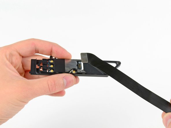
Remove the three Phillips screws securing the AirPort/Bluetooth board to the AirPort/Bluetooth board housing.
-
Use the flat end of a spudger to dislodge the AirPort/Bluetooth board from its recess in the AirPort/Bluetooth board housing.
-
-
Questo passaggio è privo di traduzione. Aiuta a tradurlo
-
Remove the AirPort/Bluetooth board from its aluminum housing.
-


Annulla: non ho completato questa guida.
Altre 82 persone hanno completato questa guida.

22 Commenti
does anybody knows if changing this boards changes too the MAC address of the wifi system??
Thanks.
Yes, MAC is associate dand it is unique with each Network interface: wireless or wired.
Hello to the community. I was wondering if i could change my MBP8.2's bluetooth dongle with a one of the newer models (MBP mid 2012 for instance) that support Bluetooth 4.0. Is it possible?
I have a 2011 MBP15. It won't link Bluetooth for Keynote with my new iphone 6+. I understand the reason is I need this upgrade on the MBP.
I'm wondering if doing the upgrade will prevent BT linking between my iPad 2 and my MBP. They can connect now.
Hi everybody! I've change my Airport/Bluetooth board on my MacBook Pro early 2011 cause I think my old board was broken. With the old board Bluetooth works correctly but about wifi board when you look on the icon at the up on right of your monitor it says " no wifi board installed" and inside the wifi icon it appear an 'X'
I buy a new board and after installation the problem was not solved.
Yes, Bluetooth work perfectly and now is 4.0 but I still had the problem of wifi. I can't connect in everyplace my MacBookPro. This is a serious problem for me. Anyone can help me?