Questa versione può contenere modifiche errate. Passa all'ultima istantanea verificata.
Cosa ti serve
-
-
Premere con le dita entrambe le linguette di sgancio della batteria verso l'esterno e sollevare la batteria dal computer.
-
-
-
Rimuovere le tre viti con testa a croce da 2 mm dallo sportello della memoria.
-
Sollevare lo sportello della memoria affinché sia possibile prenderlo e farlo scorrere verso di sé, estraendolo dall'alloggiamento.
-
-
-
Rimuovere le due viti con testa a croce da 2,8 mm nello scomparto della batteria in prossimità della chiusura.
-
-
-
Sollevare il case dalla parte posteriore e, mediante le dita, liberarlo progressivamente dai lati. Dopo aver liberato i fianchi, potrebbe essere necessario inclinare il case verso l'alto e verso il basso per liberare la parte anteriore del case superiore.
-
Sono presenti quattro levette di plastica sopra lo slot del DVD e in alto e a sinistra del sensore infrarossi. Queste levette potrebbero essere difficili da sganciare senza fare leva. Inoltre, potrebbe essere difficile riagganciarle durante il riassemblaggio.
-
-
Questo passaggio è privo di traduzione. Aiuta a tradurlo
-
Disconnect the two or three antenna cables attached to the Airport Extreme card. Depending on your model, one of the three cables may be unused and capped with a black shrink tube.
-
-
Questo passaggio è privo di traduzione. Aiuta a tradurlo
-
Deroute the Airport antenna cables from their channel in the left speaker.
-
-
Questo passaggio è privo di traduzione. Aiuta a tradurlo
-
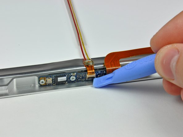
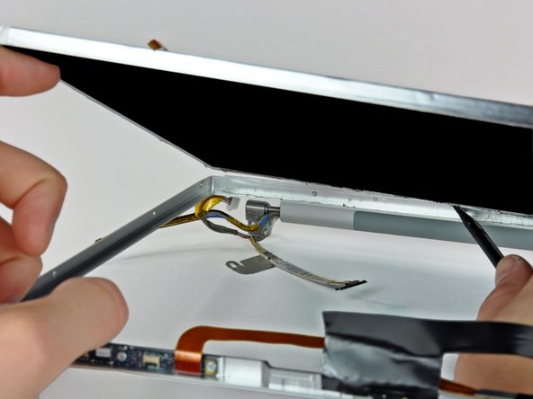
Disconnect the iSight cable from the logic board by sliding the cable to the left and out of its connector.
-
-
-
Questo passaggio è privo di traduzione. Aiuta a tradurlo
-
Support the display with one hand while removing the following screws:
-
One 9.5 mm silver T6 Torx screw with threads on only 3 mm of the shaft on the inside of the display hinges.
-
One 9.5 mm silver T6 Torx screw with threads on the entire shaft on the outside of the left hinge.
-
One 9.2 mm full thread T6 Torx screw securing the iSight cable ground loop to the fan.
-
-
Questo passaggio è privo di traduzione. Aiuta a tradurlo
-
Disconnect the inverter cable from the left I/O board by placing a spudger beneath the cable and lifting up.
-
-
Questo passaggio è privo di traduzione. Aiuta a tradurlo
-
Disconnect the display data cable from the logic board.
-
Remove the foam bumper from the top of the right hinge of the display.
-
-
Questo passaggio è privo di traduzione. Aiuta a tradurlo
-
Remove the silver 9.2 mm T6 Torx securing the ground loop in the display data cable to the casing.
-
-
Questo passaggio è privo di traduzione. Aiuta a tradurlo
-
Support the display with one hand while removing the following screw:
-
One 9.5 mm silver T6 Torx screw with threads on only 3 mm of the shaft on the inside of the display hinges.
-
-
Questo passaggio è privo di traduzione. Aiuta a tradurlo
-
Grasp the display assembly on both sides and lift it up and out of the computer.
-
-
Questo passaggio è privo di traduzione. Aiuta a tradurlo
-
Remove the 4.5 mm Phillips screws from the lower left and right corners of the display (two screws total). These screws have a .8 mm thick head.
-
-
Questo passaggio è privo di traduzione. Aiuta a tradurlo
-
Insert the flat end of a spudger perpendicular to the face of the display between the plastic strip attached to the rear bezel and the front bezel.
-
With the spudger still inserted, rotate it away from the display to separate the front and rear bezels.
-
Work along the right edge of the display until the rear bezel is evenly separated from the front bezel.
-
-
Questo passaggio è privo di traduzione. Aiuta a tradurlo
-
Insert your spudger between the front and rear display bezels at the lower right corner of the display.
-
Pry the rear bezel away from the front bezel to slightly separate the bottom edge of the rear display bezel.
-
-
Questo passaggio è privo di traduzione. Aiuta a tradurlo
-
Insert the flat end of a spudger into the gap between the rear display bezel and the clutch cover.
-
Twist the spudger to separate the lower edge of the rear display bezel from the clutch cover.
-
Work along the lower edge of the rear bezel until it is evenly separated from the clutch cover.
-
-
Questo passaggio è privo di traduzione. Aiuta a tradurlo
-
Now that the right and bottom edges of the rear bezel are slightly separated from the front bezel, use a spudger to pop the rear bezel off the tabs near the lower right corner of the display.
-
-
Questo passaggio è privo di traduzione. Aiuta a tradurlo
-
Insert the flat end of a spudger between the front bezel and the plastic strip attached to the rear bezel near the screw holes at the bottom corners of the display.
-
Rotate your spudger toward the rear bezel to separate it from the front bezel.
-
-
Questo passaggio è privo di traduzione. Aiuta a tradurlo
-
Slightly lift the lower edge of the display and pull it away from the rear display bezel.
-
Go here for the guide to continue replacing the screen: MacBook Pro 15" Core 2 Duo Models A1226 and A1260 LCD Panel Replacement
-
-
Questo passaggio è privo di traduzione. Aiuta a tradurlo
-
Peel the large piece of black tape off the LCD near the latches at the top edge of the display.
-
-
Questo passaggio è privo di traduzione. Aiuta a tradurlo
-
Remove the two pieces of tape covering the iSight and camera ribbon cables near the top of the display.
-
-
Questo passaggio è privo di traduzione. Aiuta a tradurlo
-
Be careful not to damage the ZIF cable retainer as you use the edge of a plastic opening tool to flip it up.
-
Pull the iSight cable out of its socket on the camera board.
-
-
Questo passaggio è privo di traduzione. Aiuta a tradurlo
-
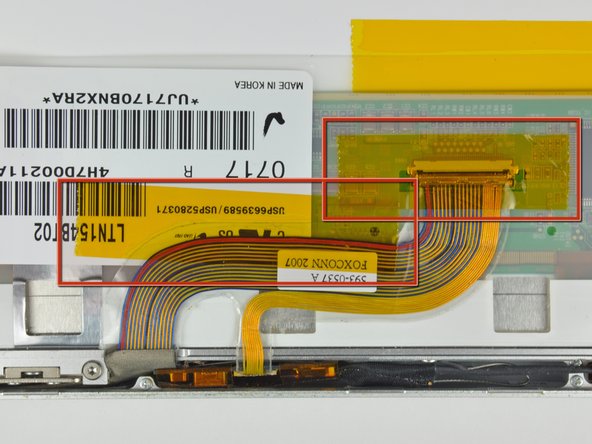
First remove the strip of tape covering the iSight cable.
-
Next, peel the three orange antenna straps off the lower edge of the LCD.
-
Remove the two pieces of tape securing the display data cable to the LCD.
-
-
Questo passaggio è privo di traduzione. Aiuta a tradurlo
-
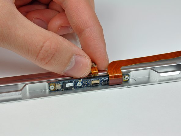
Disconnect the display data cable by pulling its connector toward the bottom edge of the display, away from the socket on the LCD.
-
-
Questo passaggio è privo di traduzione. Aiuta a tradurlo
-
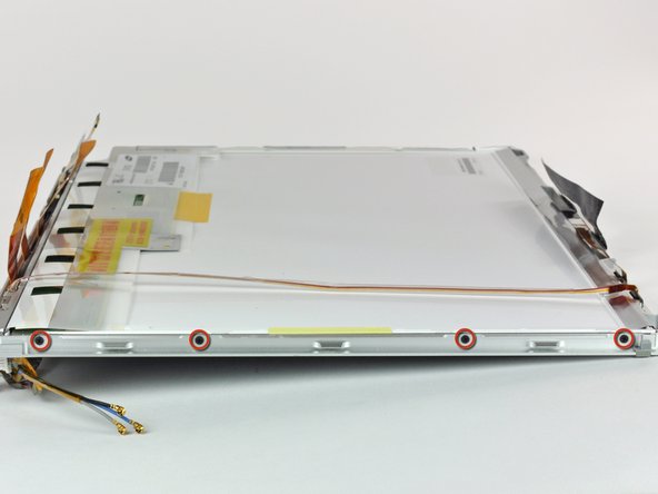
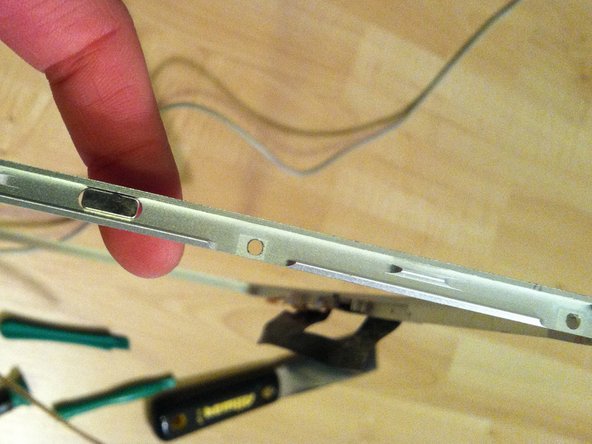
Remove the four 3 mm Phillips screws from each side of the display (eight screws total).
-
-
Questo passaggio è privo di traduzione. Aiuta a tradurlo
-
Do not simply pry on the edge of the frame as it is made of aluminum and can very easily bend!
-
Use the flat end of a spudger to gently lift one of the top corners of the LCD out of the front bezel.
-
-
Questo passaggio è privo di traduzione. Aiuta a tradurlo
-
Work your way along the top edge of the LCD, slowly prying the attached steel strip away from the front bezel.
-
-
Questo passaggio è privo di traduzione. Aiuta a tradurlo
-
Now that the top edge is free, slightly lift the LCD out of the front bezel for enough room to pry the steel strip along the lower edge of the LCD away from the front bezel.
-
Pry along the lower edge of the LCD until it is freed from the adhesive on the front bezel.
-
Avoid pulling the edge of the LCD unit from the screen. Be sure to insert the tool between the metal of the bezel and the metal of the LCD. If the adhesive is very strong, make a couple trips across the bottom edge to avoid applying too much pressure.
-
-
Questo passaggio è privo di traduzione. Aiuta a tradurlo
-
Lift the LCD out of the front bezel, minding any cables that may get caught.
-


Annulla: non ho completato questa guida.
Altre 139 persone hanno completato questa guida.

7 Commenti
I didn't have any trouble getting this apart - I used a small screwdriver from a jewelry repair kit (the set of six super small screwdrivers). I slide it in on the left front where it was open and slid it towards the IR thing. After that clip opened up I just slid it over towards the DVD drive... presto. Will update when I put this back together in a couple days. This guide should warn in the beginning to keep the screws identified in some way or you'll have a %*^! of time putting it back together.
I didn't have a spudger handy, but I got by just fine using an old credit card. Don't use a current one, as I dented up the edges pretty good in the process.
I've disassembled many a pc laptop without instructions, but macs are special ;) it was very helpful to have all the details spelled out for me. Thanks!
Be very carefull and bee patience. It´s very helpfull to have something like the ifixit magnetic project mat to keep the screws in order, otherwise you will have a hard time to put the parts together.