Questa versione può contenere modifiche errate. Passa all'ultima istantanea verificata.
Cosa ti serve
-
-
Premere con le dita entrambe le linguette di sgancio della batteria verso l'esterno e sollevare la batteria dal computer.
-
-
-
Rimuovere le tre viti con testa a croce da 2 mm dallo sportello della memoria.
-
Sollevare lo sportello della memoria affinché sia possibile prenderlo e farlo scorrere verso di sé, estraendolo dall'alloggiamento.
-
-
-
Rimuovere le due viti con testa a croce da 2,8 mm nello scomparto della batteria in prossimità della chiusura.
-
-
-
Sollevare il case dalla parte posteriore e, mediante le dita, liberarlo progressivamente dai lati. Dopo aver liberato i fianchi, potrebbe essere necessario inclinare il case verso l'alto e verso il basso per liberare la parte anteriore del case superiore.
-
Sono presenti quattro levette di plastica sopra lo slot del DVD e in alto e a sinistra del sensore infrarossi. Queste levette potrebbero essere difficili da sganciare senza fare leva. Inoltre, potrebbe essere difficile riagganciarle durante il riassemblaggio.
-
-
Questo passaggio è privo di traduzione. Aiuta a tradurlo
-
Disconnect the two or three antenna cables attached to the Airport Extreme card. Depending on your model, one of the three cables may be unused and capped with a black shrink tube.
-
-
Questo passaggio è privo di traduzione. Aiuta a tradurlo
-
Deroute the Airport antenna cables from their channel in the left speaker.
-
-
Questo passaggio è privo di traduzione. Aiuta a tradurlo
-
Disconnect the iSight cable from the logic board by sliding the cable to the left and out of its connector.
-
-
-
Questo passaggio è privo di traduzione. Aiuta a tradurlo
-
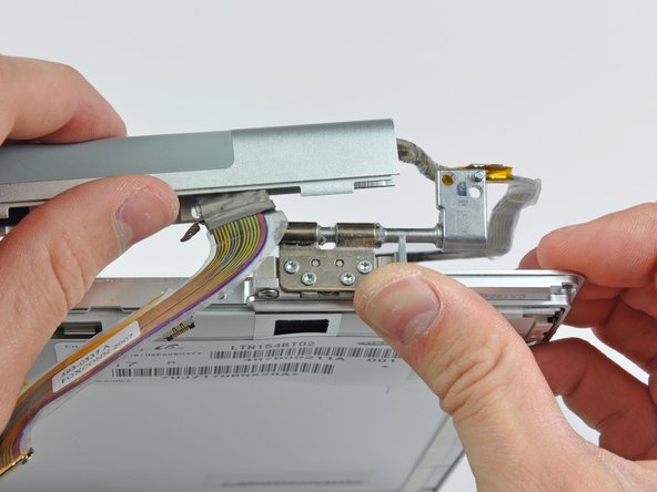
Support the display with one hand while removing the following screws:
-
One 9.5 mm silver T6 Torx screw with threads on only 3 mm of the shaft on the inside of the display hinges.
-
One 9.5 mm silver T6 Torx screw with threads on the entire shaft on the outside of the left hinge.
-
One 9.2 mm full thread T6 Torx screw securing the iSight cable ground loop to the fan.
-
-
Questo passaggio è privo di traduzione. Aiuta a tradurlo
-
Disconnect the inverter cable from the left I/O board by placing a spudger beneath the cable and lifting up.
-
-
Questo passaggio è privo di traduzione. Aiuta a tradurlo
-
Disconnect the display data cable from the logic board.
-
Remove the foam bumper from the top of the right hinge of the display.
-
-
Questo passaggio è privo di traduzione. Aiuta a tradurlo
-
Remove the silver 9.2 mm T6 Torx securing the ground loop in the display data cable to the casing.
-
-
Questo passaggio è privo di traduzione. Aiuta a tradurlo
-
Support the display with one hand while removing the following screw:
-
One 9.5 mm silver T6 Torx screw with threads on only 3 mm of the shaft on the inside of the display hinges.
-
-
Questo passaggio è privo di traduzione. Aiuta a tradurlo
-
Grasp the display assembly on both sides and lift it up and out of the computer.
-
-
Questo passaggio è privo di traduzione. Aiuta a tradurlo
-
Remove the 4.5 mm Phillips screws from the lower left and right corners of the display (two screws total). These screws have a .8 mm thick head.
-
-
Questo passaggio è privo di traduzione. Aiuta a tradurlo
-
Insert the flat end of a spudger perpendicular to the face of the display between the plastic strip attached to the rear bezel and the front bezel.
-
With the spudger still inserted, rotate it away from the display to separate the front and rear bezels.
-
Work along the right edge of the display until the rear bezel is evenly separated from the front bezel.
-
-
Questo passaggio è privo di traduzione. Aiuta a tradurlo
-
Insert your spudger between the front and rear display bezels at the lower right corner of the display.
-
Pry the rear bezel away from the front bezel to slightly separate the bottom edge of the rear display bezel.
-
-
Questo passaggio è privo di traduzione. Aiuta a tradurlo
-
Insert the flat end of a spudger into the gap between the rear display bezel and the clutch cover.
-
Twist the spudger to separate the lower edge of the rear display bezel from the clutch cover.
-
Work along the lower edge of the rear bezel until it is evenly separated from the clutch cover.
-
-
Questo passaggio è privo di traduzione. Aiuta a tradurlo
-
Now that the right and bottom edges of the rear bezel are slightly separated from the front bezel, use a spudger to pop the rear bezel off the tabs near the lower right corner of the display.
-
-
Questo passaggio è privo di traduzione. Aiuta a tradurlo
-
Insert the flat end of a spudger between the front bezel and the plastic strip attached to the rear bezel near the screw holes at the bottom corners of the display.
-
Rotate your spudger toward the rear bezel to separate it from the front bezel.
-
-
Questo passaggio è privo di traduzione. Aiuta a tradurlo
-
Slightly lift the lower edge of the display and pull it away from the rear display bezel.
-
Go here for the guide to continue replacing the screen: MacBook Pro 15" Core 2 Duo Models A1226 and A1260 LCD Panel Replacement
-
-
Questo passaggio è privo di traduzione. Aiuta a tradurlo
-
Use the tip of a spudger to lift the LED driver board out of the clutch cover.
-
-
Questo passaggio è privo di traduzione. Aiuta a tradurlo
-
Disconnect the backlight cable by pulling its connector away from the socket on the LED driver board.
-
-
Questo passaggio è privo di traduzione. Aiuta a tradurlo
-
Disconnect the LED driver cable by pulling its connector away from the socket on the inverter board.
-
Remove the LED driver board and set it aside.
-
-
Questo passaggio è privo di traduzione. Aiuta a tradurlo
-
Remove the two pieces of kapton tape covering the display data cable.
-
Remove the strip of tape securing the iSight cable to the LCD.
-
Peel the three antenna straps off the lower edge of the LCD.
-
-
Questo passaggio è privo di traduzione. Aiuta a tradurlo
-
Disconnect the display data cable by pulling its connector toward the bottom edge of the display, away from the socket on the LCD.
-
-
Questo passaggio è privo di traduzione. Aiuta a tradurlo
-
Remove the two Phillips screws securing the ground straps for the display data cable and LED driver board cable to the clutch cover.
-
-
Questo passaggio è privo di traduzione. Aiuta a tradurlo
-
Remove the Phillips screw hidden behind the display data cable.
-
-
Questo passaggio è privo di traduzione. Aiuta a tradurlo
-
Remove the three Phillips screws behind antenna straps along the bottom edge of the display.
-
-
Questo passaggio è privo di traduzione. Aiuta a tradurlo
-
To remove the clutch assembly, first insert the flat end of a spudger into the gap between the clutch hinge and the clutch cover where the cables exit.
-
While prying the clutch assembly away from the clutch hinge with your spudger, use a plastic opening tool to increase the gap between the clutch cover and the front display bezel.
-
Work your way along the length of the clutch cover to fully separate the adhesive.
-
-
Questo passaggio è privo di traduzione. Aiuta a tradurlo
-
Push the clutch assembly off each of the clutch hinges and remove it from the display.
-
-
Questo passaggio è privo di traduzione. Aiuta a tradurlo
-
De-route the display data cable from around the right clutch hinge and remove it from the front bezel.
-


Annulla: non ho completato questa guida.
Altre 39 persone hanno completato questa guida.

2 Commenti
hello great tutorial thanks a lot i have a idiot question in my mind is it possible to use this screen with a macbook 13 inch 2009
Thanks, great instrucs! Could use a couple more images at the end to show how that convoluted video cable fits into the hinge slot, but after staring at it a while I managed to work it into place.