Questa versione può contenere modifiche errate. Passa all'ultima istantanea verificata.
Cosa ti serve
-
Questo passaggio è privo di traduzione. Aiuta a tradurlo
-
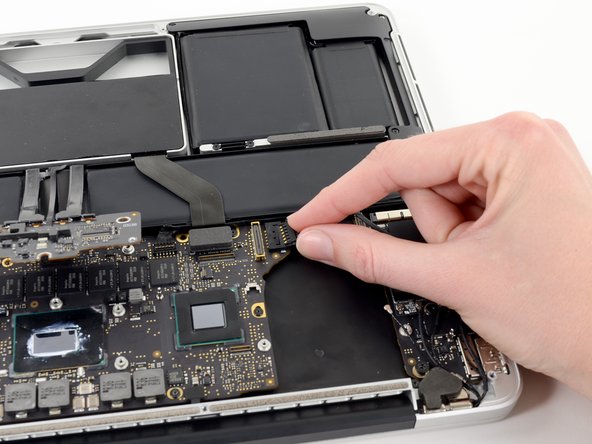
Use the tip of a spudger to push the edges of the I/O board connector straight out of its socket on the logic board.
-
-
Questo passaggio è privo di traduzione. Aiuta a tradurlo
-
Wedge the flat end of a spudger underneath the keyboard backlight connector and the logic board.
-
Gently twist the flat end of a spudger upwards to pry the keyboard backlight connector up off its socket on the logic board.
-
-
Questo passaggio è privo di traduzione. Aiuta a tradurlo
-
Grab the black pull tab secured to the display data cable lock and rotate it toward the DC-In side of the computer.
-
Pull the display data cable straight out of its socket on the logic board.
-
-
Questo passaggio è privo di traduzione. Aiuta a tradurlo
-
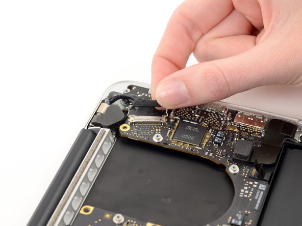
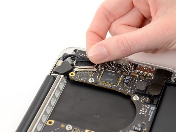
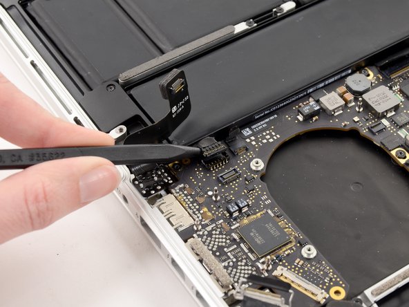
Pry the headphone jack cable connector up off its socket on the logic board.
-
-
-
Questo passaggio è privo di traduzione. Aiuta a tradurlo
-
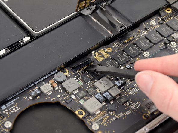
Use the tip of a spudger to flip up the retaining flap on the microphone ribbon cable ZIF socket.
-
Grasp the plastic pull tab and pull the microphone ribbon cable out of its socket.
-
-
Questo passaggio è privo di traduzione. Aiuta a tradurlo
-
Use the flat edge of a spudger to flip up the retaining flap on the keyboard ribbon cable ZIF socket.
-
Grasp the plastic pull tab and pull the keyboard ribbon cable out of its socket.
-
-
Questo passaggio è privo di traduzione. Aiuta a tradurlo
-
Repeat the previous procedure to disconnect the Trackpad ribbon cable from its socket on the logic board.
-
-
Questo passaggio è privo di traduzione. Aiuta a tradurlo
-
Wedge the flat end of a spudger beneath the right speaker cable connector.
-
Gently pry the right speaker cable connector up off from its socket on the logic board.
-
-
Questo passaggio è privo di traduzione. Aiuta a tradurlo
-
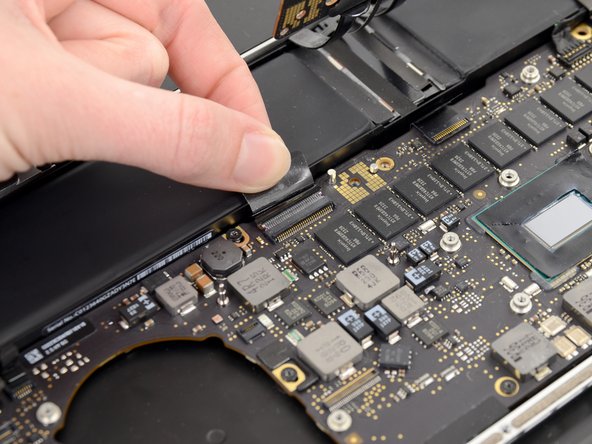
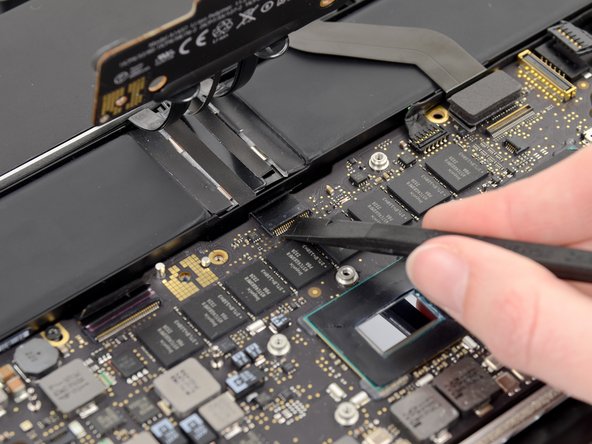
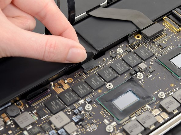
Use the flat end of a spudger to pry the SSD cable connector up off its socket on the logic board.
-
-
Questo passaggio è privo di traduzione. Aiuta a tradurlo
-
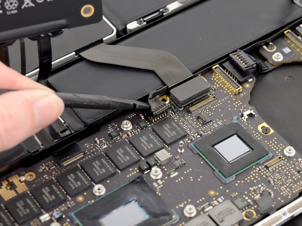
Wedge the tip of a spudger beneath the left speaker cable connector.
-
Gently pry the left speaker cable connector up off from its socket on the logic board.
-
-
Questo passaggio è privo di traduzione. Aiuta a tradurlo
-
Remove the nine 3.3 mm T5 Torx screws securing the logic board and MagSafe DC-in board to the upper case.
-
-
Questo passaggio è privo di traduzione. Aiuta a tradurlo
-
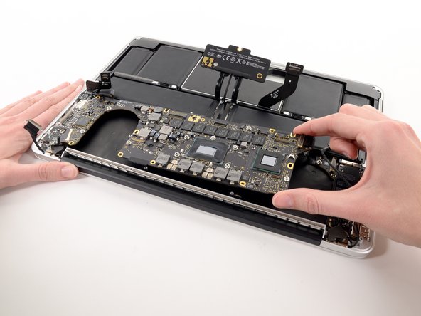
Carefully grasp the corner of the logic board (opposite of the I/O ports) and lift the logic board out of the upper case.
-