Questa versione può contenere modifiche errate. Passa all'ultima istantanea verificata.
Cosa ti serve
-
-
Rimuovi le 10 viti seguenti che fissano il coperchio inferiore al case superiore:
-
Due viti Pentalobe da 2,3 mm
-
Otto viti Pentalobe da 3,0 mm
-
-
-
Rimuovi la copertura in plastica attaccata alla scheda dei contatti della batteria.
-
-
-
-
Afferra con delle pinzette l'interposer.
-
Solleval'interposer dalla scheda logica e rimuovilo.
-
-
Questo passaggio è privo di traduzione. Aiuta a tradurlo
-
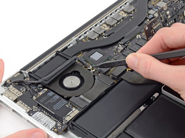
Use the tip of a spudger to push the iSight camera cable connector straight away from its socket on the logic board.
-
-
Questo passaggio è privo di traduzione. Aiuta a tradurlo
-
Use the flat end of a spudger to pry and disconnect the three antenna cable connectors from the AirPort board.
-
The three cables are coded with black sleeves of different lengths. During reassembly:
-
Connect the long-sleeved cable to the socket closest to the ports.
-
The short-sleeved cable connects next to the screw.
-
The remaining cable has no sleeve, and connects in the last empty socket, next to the fan.
-
-
Questo passaggio è privo di traduzione. Aiuta a tradurlo
-
Move the antenna cables aside, clear of the AirPort board.
-
-
Questo passaggio è privo di traduzione. Aiuta a tradurlo
-
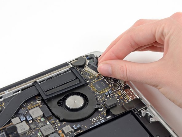
Grab the black pull tab secured to the display data cable lock and rotate it toward the DC-In side of the computer.
-
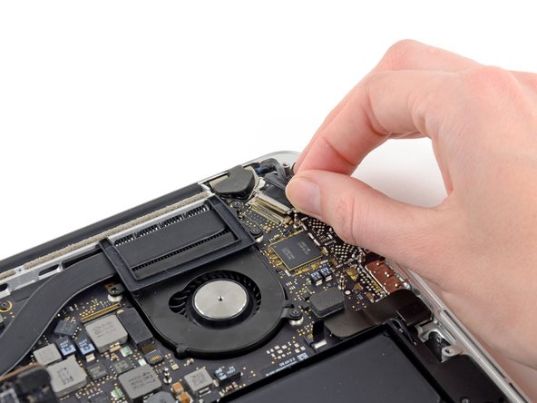
Pull the display data cable straight out of its socket on the logic board.
-
-
Questo passaggio è privo di traduzione. Aiuta a tradurlo
-
Use a pair of tweezers to lift the rubber hinge covers up off the right and left display hinges.
-
-
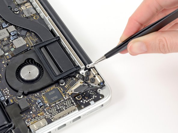
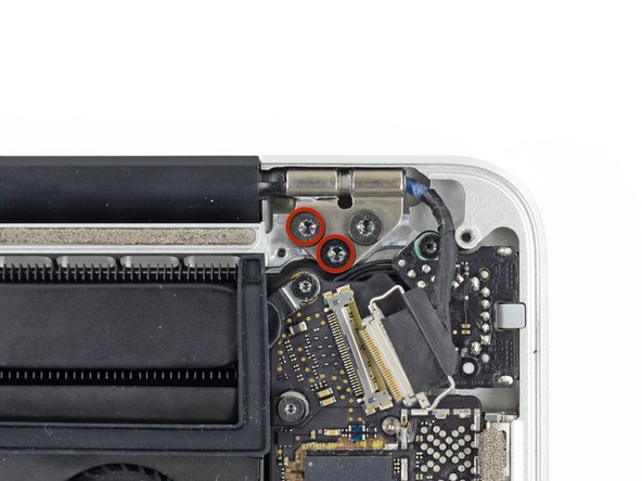
Questo passaggio è privo di traduzione. Aiuta a tradurlo
-
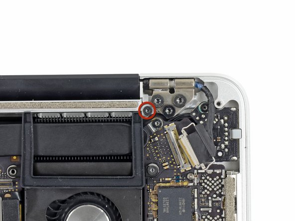
Remove the two 3.1 mm T5 Torx screws securing the aluminum hinge brackets.
-
-
Questo passaggio è privo di traduzione. Aiuta a tradurlo
-
Use a pair of tweezers to lift aluminum hinge brackets off the right and left display hinges.
-
-
Questo passaggio è privo di traduzione. Aiuta a tradurlo
-
Remove the four inner 5.3 mm T8 Torx screws (two on each side) securing the display to the upper case.
-
-
Questo passaggio è privo di traduzione. Aiuta a tradurlo
-
While holding the display and upper case together with your left hand, remove the remaining T8 Torx screw from the upper display bracket.
-
Remove the last remaining T8 Torx screw securing the display to the upper case.
-
-
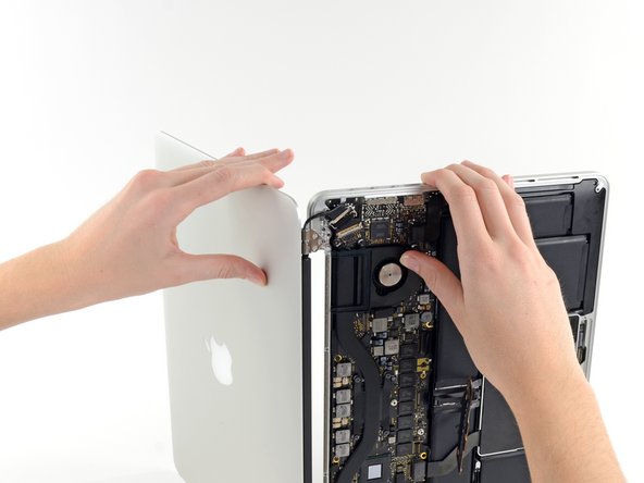
Questo passaggio è privo di traduzione. Aiuta a tradurlo
-
Grip both halves of the device, one in each hand.
-
Gently push forward on the bottom half of the device to detach it from the display assembly.
-
Carefully set each component aside, making sure to set down the lower half keyboard-side down.
-


Annulla: non ho completato questa guida.
Altre 57 persone hanno completato questa guida.

9 Commenti
The screen arrived 1 day ahead of schedule. The "A" level screen was in perfect condition. I replaced the display in about 1 hour using the above instructions, powered up and everything worked perfectly.
My screen was wobbling, after removing the display, and tightening the screws on the display (after removing the black case at the bottom of the display, if you slide it to the right you can pull the black case of the display) the issue was fixed.
Excellent guide, walked through the steps and in reverse without any problems except removal of the bottom case. The P5 pentalobe has been such a headache. I ended up using a drill to grind down the heads (which was scary and probably incorrect) after stripping them. Now I'm looking for a way to extract the shafts. However, rest of the process once in was a dream.
Excellent guide, helped me to fix my wobbling screen.