Salta al contenuto principale

Questa versione può contenere modifiche errate. Passa all'ultima istantanea verificata.

Cosa ti serve

  1. , Case inferiore: passo 1, immagine 1 di 1
    Attrezzo utilizzato in questo passaggio:
    Magnetic Project Mat
    $19.95
    Compra
    • Rimuovi le 10 viti seguenti che fissano il coperchio inferiore al case superiore:

    • Due viti Pentalobe da 2,3 mm

    • Otto viti Pentalobe da 3,0 mm

    • Nel corso dell'intera procedura, tieni traccia di ogni vite e accertati che ritorni esattamente al suo posto per evitare di danneggiare il dispositivo.

  2. : passo 2, immagine 1 di 1
    • Infila le tue dita tra il case superiore e quello inferiore.

    • Con delicatezza, tira il coperchio inferiore per staccarlo da quello superiore.

    • Rimuovi il case inferiore e mettilo da parte.

  3. : passo 3, immagine 1 di 3 : passo 3, immagine 2 di 3 : passo 3, immagine 3 di 3
    • Durante il rimontaggio, spingi con delicatezza il centro del case inferiore per riattaccare le due clip in plastica.

    • Il case inferiore è collegato a quello superiore con due clip di plastica in posizione centrale.

  4. , Connettore batteria: passo 4, immagine 1 di 1
    • Rimuovi la copertura in plastica attaccata alla scheda dei contatti della batteria.

  5. : passo 5, immagine 1 di 1
    • Rimuovi le seguenti viti che fissano la scheda del connettore della batteria alla scheda logica:

    • Due viti Torx T6 da 2,8 mm

    • Una vite a colletto Torx T6 da 7,0 mm

  6. : passo 6, immagine 1 di 2 : passo 6, immagine 2 di 2
    • Usa delle pinzette per rimuovere il piccolo coperchio in plastica posizionato vicino alla parte inferiore destra della scheda del connettore della batteria.

  7. : passo 7, immagine 1 di 1
    • Rimuovi la vite a testa larga Torx T6 da 6,4 mm che fissa il connettore della batteria al gruppo della scheda logica.

  8. : passo 8, immagine 1 di 2 : passo 8, immagine 2 di 2
    • Solleva con delicatezza dalla scheda logica la scheda del connettore della batteria.

    • Si raccomanda di piegare poco i cavi della batteria, quanto basta per tenere la scheda sospesa sopra alla scheda logica, dove non dà fastidio.

    • Non ribaltate completamente la scheda e non piegati i cavi, perché questo potrebbe danneggiare la batteria.

  9. , Scheda contatti batteria: passo 9, immagine 1 di 2 , Scheda contatti batteria: passo 9, immagine 2 di 2
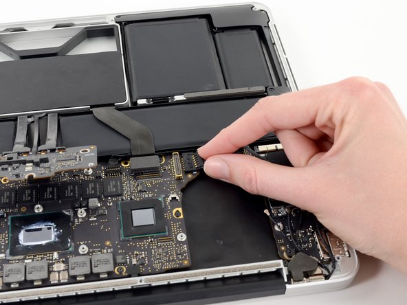
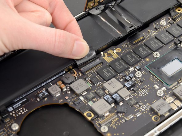
    • Afferra con delle pinzette l'interposer.

    • Interposer è il nome di un'interfaccia elettrica che collega una connessione elettrica ad un'altra. In questa riparazione è la scheda che connette la batteria alla scheda logica.

    • Solleval'interposer dalla scheda logica e rimuovilo.

    • La rimozione di questa scheda assicura che la batteria resti disconnesso durante la tua riparazione, evitando del tuo computer possa accidentalmente accendersi. È anche una buona idea allontanarlo in modo che non possa ricadere inaspettatamente.

  10. Questo passaggio è privo di traduzione. Aiuta a tradurlo

    : passo 10, immagine 1 di 1
    • Remove the following screws securing the heat sink to the logic board assembly:

    • One 2.4 mm Phillips #00 screw

    • One 3.4 mm T5 Torx screw

    • Four 2.7 mm T5 Torx screws

  11. Questo passaggio è privo di traduzione. Aiuta a tradurlo

    : passo 11, immagine 1 di 2 : passo 11, immagine 2 di 2
    • Lift and remove the heat sink up off the logic board assembly.

    • When reinstalling the heat sink, be sure to apply a new layer of thermal paste. If you have never applied thermal paste before, we have a guide that makes it easy.

  12. Questo passaggio è privo di traduzione. Aiuta a tradurlo

    : passo 12, immagine 1 di 2 : passo 12, immagine 2 di 2
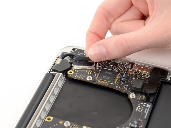
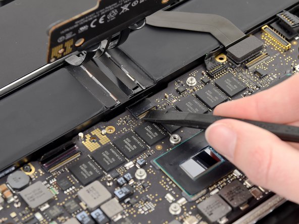
    • Use the flat end of a spudger to pry the right side of the I/O board data cable connector up off its socket on the I/O board.

    • When prying the I/O board data cable connector from its socket, make sure to pry the connector itself and not the socket. Prying the socket may cause irreversible damage to the I/O board.

  13. Questo passaggio è privo di traduzione. Aiuta a tradurlo

    : passo 13, immagine 1 di 2 : passo 13, immagine 2 di 2
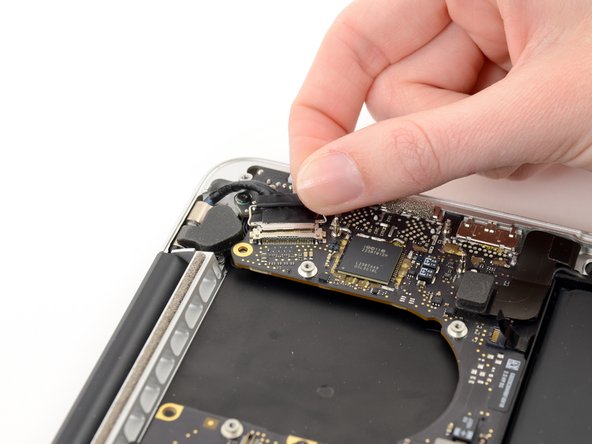
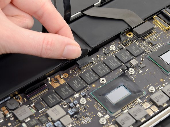
    • Wedge the flat end of a spudger beneath the left side of the I/O board data cable connector.

    • Gently twist the spudger to disconnect the I/O board data cable connector from its socket on the logic board.

  14. Questo passaggio è privo di traduzione. Aiuta a tradurlo

    : passo 14, immagine 1 di 1
    • Lift and remove the I/O board data cable from the MacBook Pro.

  15. Questo passaggio è privo di traduzione. Aiuta a tradurlo

    : passo 15, immagine 1 di 2 : passo 15, immagine 2 di 2
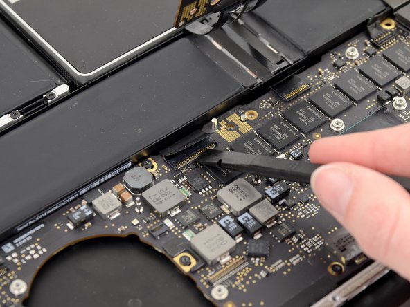
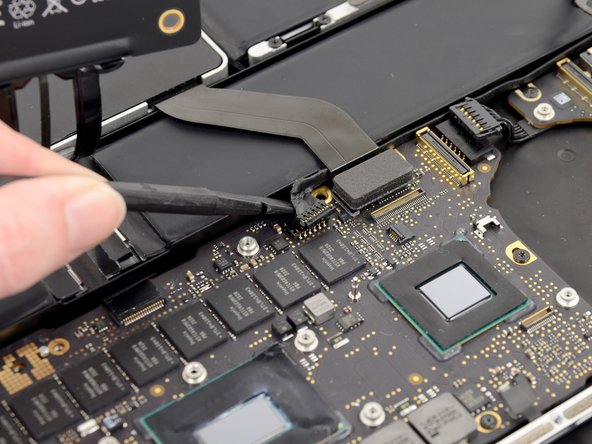
    • Use the tip of a spudger to push the iSight camera cable connector straight away from its socket on the logic board.

    • It is recommended to carefully push on both sides of the connector to "walk" it out of its socket.

  16. Questo passaggio è privo di traduzione. Aiuta a tradurlo

    : passo 16, immagine 1 di 2 : passo 16, immagine 2 di 2
    • Move the iSight camera cable aside.

  17. Questo passaggio è privo di traduzione. Aiuta a tradurlo

    : passo 17, immagine 1 di 3 : passo 17, immagine 2 di 3 : passo 17, immagine 3 di 3
    • Use the tip of a spudger to flip up the retaining flap on the right fan ribbon cable ZIF socket.

    • Be sure you are prying up on the hinged retaining flap, not the socket itself.

    • Pull the right fan ribbon cable straight out of its socket on the logic board.

  18. Questo passaggio è privo di traduzione. Aiuta a tradurlo

    : passo 18, immagine 1 di 1
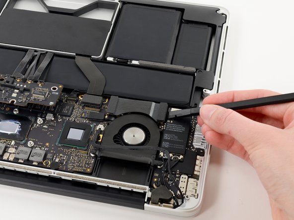
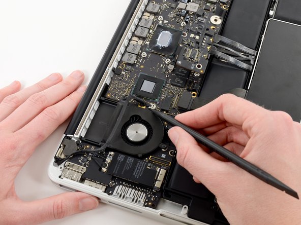
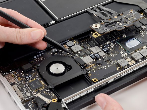
    • Remove the three 3.1 mm T5 Torx screws securing the right fan to the logic board assembly.

  19. Questo passaggio è privo di traduzione. Aiuta a tradurlo

    : passo 19, immagine 1 di 1
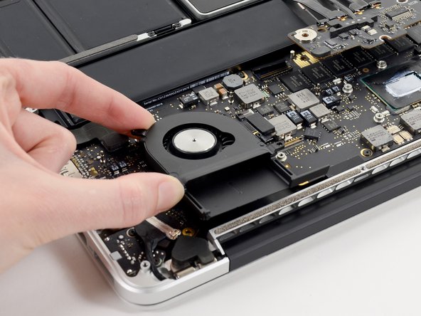
    • Lift and remove the right fan out of the upper case.

  20. Questo passaggio è privo di traduzione. Aiuta a tradurlo

    : passo 20, immagine 1 di 2 : passo 20, immagine 2 di 2
    • Use the tip of a spudger to flip up the retaining flap on the left fan ribbon cable ZIF socket.

    • Be sure you are prying up on the hinged retaining flap, not the socket itself.

  21. Questo passaggio è privo di traduzione. Aiuta a tradurlo

    : passo 21, immagine 1 di 1
    • Remove the three 3.1 mm T5 Torx screws securing the left fan to the logic board assembly.

  22. Questo passaggio è privo di traduzione. Aiuta a tradurlo

    : passo 22, immagine 1 di 2 : passo 22, immagine 2 di 2
    • Lift and remove the left fan out of the upper case.

    • Make sure to pull the left fan straight away to simultaneously pull the left fan ribbon cable out of its socket on the logic board.

  23. Questo passaggio è privo di traduzione. Aiuta a tradurlo

    : passo 23, immagine 1 di 3 : passo 23, immagine 2 di 3 : passo 23, immagine 3 di 3
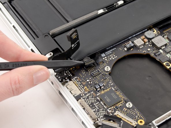
    • Use the tip of a spudger to push the edges of the I/O board connector straight out of its socket on the logic board.

    • It is recommended to carefully push on both sides of the connector to "walk" it out of its socket.

  24. Questo passaggio è privo di traduzione. Aiuta a tradurlo

    : passo 24, immagine 1 di 2 : passo 24, immagine 2 di 2
    • Wedge the flat end of a spudger underneath the keyboard backlight connector and the logic board.

    • Gently twist the flat end of a spudger upwards to pry the keyboard backlight connector up off its socket on the logic board.

  25. Questo passaggio è privo di traduzione. Aiuta a tradurlo

    : passo 25, immagine 1 di 3 : passo 25, immagine 2 di 3 : passo 25, immagine 3 di 3
    • Grab the black pull tab secured to the display data cable lock and rotate it toward the DC-In side of the computer.

    • Pull the display data cable straight out of its socket on the logic board.

    • Do not lift up on the display data cable, as its socket is very fragile. Pull the cable parallel to the face of the logic board.

  26. Questo passaggio è privo di traduzione. Aiuta a tradurlo

    : passo 26, immagine 1 di 1
    • Pry the headphone jack cable connector up off its socket on the logic board.

  27. Questo passaggio è privo di traduzione. Aiuta a tradurlo

    : passo 27, immagine 1 di 3 : passo 27, immagine 2 di 3 : passo 27, immagine 3 di 3
    • Use the tip of a spudger to flip up the retaining flap on the microphone ribbon cable ZIF socket.

    • Be sure you are prying up on the hinged retaining flap, not the socket itself.

    • Grasp the plastic pull tab and pull the microphone ribbon cable out of its socket.

  28. Questo passaggio è privo di traduzione. Aiuta a tradurlo

    : passo 28, immagine 1 di 3 : passo 28, immagine 2 di 3 : passo 28, immagine 3 di 3
    • Use the flat edge of a spudger to flip up the retaining flap on the keyboard ribbon cable ZIF socket.

    • Be sure you are prying up on the hinged retaining flap, not the socket itself.

    • Grasp the plastic pull tab and pull the keyboard ribbon cable out of its socket.

  29. Questo passaggio è privo di traduzione. Aiuta a tradurlo

    : passo 29, immagine 1 di 3 : passo 29, immagine 2 di 3 : passo 29, immagine 3 di 3
    • Repeat the previous procedure to disconnect the Trackpad ribbon cable from its socket on the logic board.

  30. Questo passaggio è privo di traduzione. Aiuta a tradurlo

    : passo 30, immagine 1 di 2 : passo 30, immagine 2 di 2
    • Wedge the flat end of a spudger beneath the right speaker cable connector.

    • Gently pry the right speaker cable connector up off from its socket on the logic board.

    • Be sure you are prying up on the connector, not the socket itself.

  31. Questo passaggio è privo di traduzione. Aiuta a tradurlo

    : passo 31, immagine 1 di 1
    • Use the flat end of a spudger to pry the SSD cable connector up off its socket on the logic board.

  32. Questo passaggio è privo di traduzione. Aiuta a tradurlo

    : passo 32, immagine 1 di 2 : passo 32, immagine 2 di 2
    • Wedge the tip of a spudger beneath the left speaker cable connector.

    • Gently pry the left speaker cable connector up off from its socket on the logic board.

    • Be sure you are prying up on the connector, not the socket itself.

  33. Questo passaggio è privo di traduzione. Aiuta a tradurlo

    : passo 33, immagine 1 di 1
    • Remove the nine 3.3 mm T5 Torx screws securing the logic board and MagSafe DC-in board to the upper case.

  34. Questo passaggio è privo di traduzione. Aiuta a tradurlo

    : passo 34, immagine 1 di 2 : passo 34, immagine 2 di 2
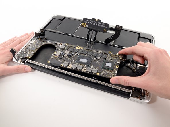
    • Carefully grasp the corner of the logic board (opposite of the I/O ports) and lift the logic board out of the upper case.

  35. Questo passaggio è privo di traduzione. Aiuta a tradurlo

    : passo 35, immagine 1 di 2 : passo 35, immagine 2 di 2
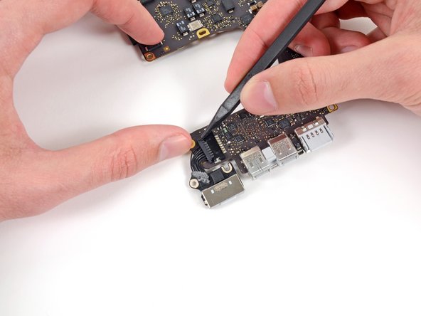
    • Gently push the edges of the MagSafe cable connector away from its socket on the logic board.

    • It is recommended "walk" the connector out of its socket. Simply push the top and bottom corners of the connector and carefully "walk it out" of its socket.

  36. Questo passaggio è privo di traduzione. Aiuta a tradurlo

    : passo 36, immagine 1 di 1
    • Pull the MagSafe cable connector straight out of its socket on the logic board.

  37. Questo passaggio è privo di traduzione. Aiuta a tradurlo

    : passo 37, immagine 1 di 1
    • Logic board remains.

Linea Traguardo

Altre 14 persone hanno completato questa guida.

Sam Goldheart

Membro da: 10/18/12

465.762 Reputazione

538 Guide realizzate

Team

iFixit Membro di iFixit

Staff

135 Membri

16.817 Guide realizzate

0 Commenti

Aggiungi Commento

Visualizza Statistiche:

Ultime 24 Ore: 1

Ultimi 7 Giorni: 11

Ultimi 30 Giorni: 55

Tutti i Tempi: 27,800