Questa versione può contenere modifiche errate. Passa all'ultima istantanea verificata.
Cosa ti serve
-
-
Usa una monetina o uno spudger per ruotare la vite di blocco della batteria di 90 gradi in senso orario.
-
-
-
Svita le tre viti con testa a croce equidistanti lungo la parete posteriore dello scomparto della batteria.
-
-
-
Rimuovere le 3 viti seguenti:
-
Una vite con testa a croce n. 00 da 11 mm nella parte centrale del case. (Testa: 5 mm di diametro x 0,75 mm di spessore)
-
Due viti con testa a croce n. 00 da 14,5 mm (testa: 5 mm di diametro x 0,75 mm di spessore)
-
-
-
Rimuovere le quattro viti con testa a croce indicate dalla parete anteriore dello scomparto della batteria. Operando da sinistra, rimuovere la seconda, la quarta, la settima e la nona vite.
-
Quattro viti con testa a croce n. 000 da 3,25 mm. (Testa: 4 mm di diametro x 4 mm di spessore)
-
-
-
Rimuovere le 4 viti seguenti dalla parte posteriore del computer:
-
La vite più lunga va nella parte interna, mentre quelle più corte nella parte esterna.
-
Due viti con testa a croce n. 00 da 11 mm con gambo (2,2 mm di diametro x 2 mm di lunghezza) (Testa: 3,2 mm di diametro x 0,5 mm di spessore)
-
Due viti con testa a croce n. 00 da 7,25 mm con gambo (2mm di diametro x 3,75 mm di lunghezza) (Testa: 3,2 mm di diametro x 0,5 mm di spessore)
-
-
-
Tenendo il case superiore sollevato, estrarre la linguetta nera del cavo argentato dal relativo connettore.
-
Con il case superiore rimosso, puoi sfruttare la possibilità di rimuovere polvere, peli, ecc. La cosa migliore è usare una bomboletta di aria compressa; se usi un pennello assicurati che sia realizzato in un materiale (di solito pelo animale) che non genera elettricità statica, potenzialmente distruttiva per l'elettronica.
-
-
-
Prendere la linguetta in plastica bianca collegata al disco rigido e tirarla verso sinistra, rimuovendo il disco dal computer.
-
-
-
Questo passaggio è privo di traduzione. Aiuta a tradurlo
-
For original Macbook Core Duo and Core 2 Duo models, remove these 3 screws:
-
Two 3 mm Phillips near the right speaker.
-
One 6 mm Phillips threaded through a hole in a plastic finger above the subwoofer.
-
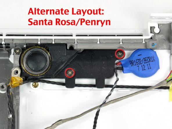
For Santa Rosa/Penryn and 2009 models, which don't have a c-channel:
-
Remove only the single 3 mm Phillips screw from the right speaker, and skip step 26.
-
-
Questo passaggio è privo di traduzione. Aiuta a tradurlo
-
Lift the right speaker out of its housing and set it to the side.
-
-
Questo passaggio è privo di traduzione. Aiuta a tradurlo
-
Using a spudger, gently pry up the white plastic slot and slide the metal c-channel to the right and away from the display.
-
-
Questo passaggio è privo di traduzione. Aiuta a tradurlo
-
Use a spudger to carefully disconnect the microphone cable from the logic board. You'll want to work from side to side, and slowly wiggle the plug back and out of its socket.
-
-
Questo passaggio è privo di traduzione. Aiuta a tradurlo
-
Lift up on the black right speaker cable with one hand, and deroute the microphone cable from the silver metal clip just above the right RAM slot.
-
-
Questo passaggio è privo di traduzione. Aiuta a tradurlo
-
If you didn't remove the ground lug retaining screw in step 20 above, remove it now. It's a 7mm (may be 4mm or 3mm in Santa Rosa/Penryn and 2009 models) Phillips screw securing the ground lugs on the right speaker cable and microphone cable to the metal frame.
-
-
Questo passaggio è privo di traduzione. Aiuta a tradurlo
-
Deroute the microphone cable and the black display data cable from the tabs at the bottom of the subwoofer.
-
-
Questo passaggio è privo di traduzione. Aiuta a tradurlo
-
Remove the single 3 mm Phillips screw securing the ground lug in the display data cable located just above the Bluetooth board. This screw may also be securing a ground lug in the speaker cable.
-
-
Questo passaggio è privo di traduzione. Aiuta a tradurlo
-
Disconnect the antenna cables from the Airport card:
-
If you have an original MacBook Core Duo or Core 2 Duo model, see the first picture, which shows that there are three antenna cables.
-
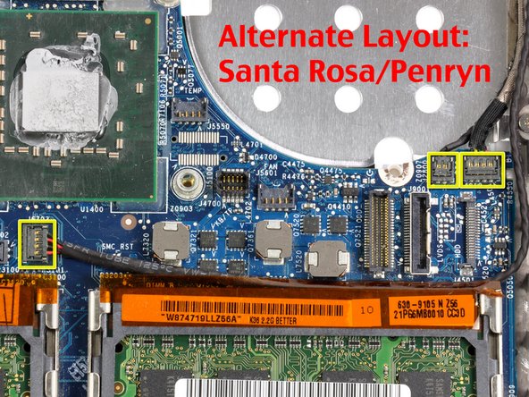
If you have a MacBook Core 2 Duo Santa Rosa/Penryn or 2009 model, there are only two antenna cables, and the plug/socket for the black inverter cable is in a different location. There may be a square foam piece over the plug/socket for the inverter board connector.
-
Disconnect the inverter cable from its socket by inserting a spudger between the right or left ends of the plug and the socket, and prying gently vertically. Do NOT pry up on the socket--you must pull up on the plug alone, vertically out of the socket. Do not pull in the direction of the cable wires or you will tear the socket off the logic board.
-
-
Questo passaggio è privo di traduzione. Aiuta a tradurlo
-
For original Macbook Core Duo and Core 2 Duo models, see first picture and remove the following 2 screws from the right hinge mount:
-
One 6 mm Phillips on the left side of the hinge mount.
-
One 10 mm Phillips on the right side of the hinge mount.
-
For Santa Rosa/Penryn and 2009 models, see second picture and remove the following 3 screws from the right hinge mount:
-
One 3 mm smalller diameter Phillips on the far left.
-
One 5.2 mm larger diameter, 4.2 mm head Phillips in the middle.
-
One 10 mm larger diameter, 4.2mm head Phillips from the far right.
-
Before removing the right hinge mount, take care to see how its pieces fit together, including the small white plastic piece. Knowing how the mount pieces fit together will help with reassembly. Lift the right hinge mount with the small white plastic piece out of the computer.
-
-
Questo passaggio è privo di traduzione. Aiuta a tradurlo
-
Hold the display with one hand while removing the following 3 screws from the left hinge mount:
-
One 7.2 mm smaller diameter Phillips from the right side.
-
One 5.2 mm larger diameter Phillips from the middle.
-
One larger diameter 10 mm Phillips from the left side.
-
Lift the left hinge mount with white plastic piece out of the computer.
-
Check that the cables coming out of the right end of the left hinge are not trapped under other cables.
-
-
Questo passaggio è privo di traduzione. Aiuta a tradurlo
-
Grasp the display assembly on either side and lift it up and out of the computer, taking care that the cables attached to the display don't snag on parts in the lower case.
-
-
Questo passaggio è privo di traduzione. Aiuta a tradurlo
-
Peel up the small black rubber cover from the right side of the heat sink.
-
-
Questo passaggio è privo di traduzione. Aiuta a tradurlo
-
Core Duo and original Core 2 Duo models (photo 1):Disconnect the two newly-revealed temperature sensor connectors and the fan connector from the logic board. These connectors move up vertically off of the logic board, NOT pulled towards the rear of the case, and can be lifted with gentle pressure from under the cable.
-
Santa Rosa/Penryn models (photo 2): There is only one temperature sensor connector containing all four wire leads.
-
Early and Mid 2009 models don't have a separate temperature sensor attached to the heat sink, and thus no cable for it, so nothing is plugged into the temperature sensor connector.
-
-
Questo passaggio è privo di traduzione. Aiuta a tradurlo
-
Remove the following 6 screws:
-
One 3 mm Phillips on the right side of the fan.
-
One 6 mm or 7mm Phillips on the left side of the fan.
-
Four 8mm or 9 mm Phillips securing the heat sink to the lower case.
-
-
Questo passaggio è privo di traduzione. Aiuta a tradurlo
-
Hold the heat sink with one hand and the fan with your other hand, and lift the heat sink and fan assembly out of the computer. The fan is attached to the heat sink only with a strip of black felt tape, so be sure to remove both parts as a unit.
-
-
Questo passaggio è privo di traduzione. Aiuta a tradurlo
-
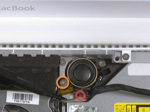
Remove the following two screws:
-
One 3mm screw securing the MagSafe board to the lower case.
-
One 7.5mm screw securing the left speaker to the lower case.
-
-
Questo passaggio è privo di traduzione. Aiuta a tradurlo
-
De-route the left speaker cable from the two clips on the left I/O frame.
-
-
Questo passaggio è privo di traduzione. Aiuta a tradurlo
-
Use a spudger to lift the left speaker out of its housing. Grasp it with your fingers and set it aside.
-
-
Questo passaggio è privo di traduzione. Aiuta a tradurlo
-
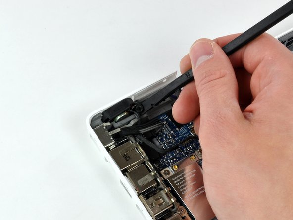
Disconnect the MagSafe board connector plug from the logic board, by grasping its cable and pulling it to the right.
-
-
Questo passaggio è privo di traduzione. Aiuta a tradurlo
-
Use your left hand to move the MagSafe board cable enough to uncover the screw at the top end of the left I/O frame.
-
Remove the 7.5 mm Phillips screw from the top end of the left I/O frame.
-
-
Questo passaggio è privo di traduzione. Aiuta a tradurlo
-
Remove the following 2 screws:
-
One 7.5 mm Phillips from the bottom end of the left I/O frame.
-
One 8 or 9 mm Phillips from the middle of the left I/O frame.
-
-
Questo passaggio è privo di traduzione. Aiuta a tradurlo
-
Lift the left I/O frame up and out of the computer. Pay attention to the thin metal EMI fingers, as they may catch as you remove the left I/O frame, especially the two fingers, above the Firewire and headphone ports, which have hooks that engage with holes in the second EMI metal shield, which runs along the front of the I/O ports.
-
-
Questo passaggio è privo di traduzione. Aiuta a tradurlo
-
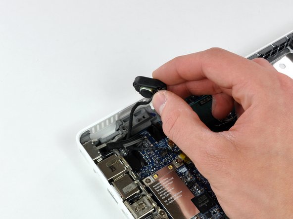
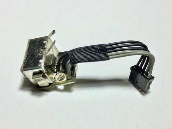
The MagSafe board is now free of all connections and can be detached freely from the logic board.
-
Using your fingers, pull out the MagSafe board.
-
-
Questo passaggio è privo di traduzione. Aiuta a tradurlo
-
Remove the two 4 mm Phillips shoulder screws attaching the battery connector to the lower case.
-
-
Questo passaggio è privo di traduzione. Aiuta a tradurlo
-
Remove the single 6.5mm Phillips screw in the upper right corner of the Airport card. This screw will have a thicker/taller cylindrical head.
-
-
Questo passaggio è privo di traduzione. Aiuta a tradurlo
-
Use a spudger to disconnect the right speaker connector and the Bluetooth connector from the logic board. Both of these connector plugs are removed by prying them gently upward, NOT by pulling them horizontally.
-
-
Questo passaggio è privo di traduzione. Aiuta a tradurlo
-
Remove the three 3 mm Phillips screws securing the logic board to the lower case.
-
-
Questo passaggio è privo di traduzione. Aiuta a tradurlo
-
Lift the logic board up from its right side, slide it to the right slightly, and then up and out of the lower case. If the I/O ports don't easily release from the left side of the housing, gently pull up the lower left corner of the logic board by pulling up on the battery connector cable.
-
-
Questo passaggio è privo di traduzione. Aiuta a tradurlo
-
Remove the two 3.5mm Phillips screws securing the subwoofer to the lower case.
-
-
Questo passaggio è privo di traduzione. Aiuta a tradurlo
-
Deroute the right speaker and Bluetooth antenna cables from their slots in the lower case.
-
-
Questo passaggio è privo di traduzione. Aiuta a tradurlo
-
Pry the Bluetooth board up from the lower case.
-
Lift the subwoofer, right speaker, Bluetooth board, and attached cables out of the computer.
-
-
Questo passaggio è privo di traduzione. Aiuta a tradurlo
-
On Santa Rosa/Penryn models, use a spudger to pry up the PRAM battery and remove it from the lower case.
-
-
Questo passaggio è privo di traduzione. Aiuta a tradurlo
-
Remove the two 6 mm Phillips shoulder screws securing the hard drive connector to the lower case.
-
-
Questo passaggio è privo di traduzione. Aiuta a tradurlo
-
Carefully lift the hard drive connector out of the case slightly, and turn it over to reveal the IR sensor's ribbon cable connector beneath. Use a spudger to flip up the tiny locking bar holding the end of the cable in place.
-
Slide the orange IR sensor cable out of its connector, and lift the hard drive connector out of the computer. The IR sensor, its ribbon cable, and its small circuit board remain in place on the lower case.
-


Annulla: non ho completato questa guida.
Altre 48 persone hanno completato questa guida.
