Introduzione
Use this guide to replace the heat sink, or remove it for reapplication of thermal paste.
Be sure to apply a new layer of thermal paste before reinstalling your heat sink.
Cosa ti serve
-
CompraAttrezzo utilizzato in questo passaggio:P5 Pentalobe Screwdriver Retina MacBook Pro and Air$5.99
-
Use a P5 Pentalobe driver to remove ten screws securing the lower case, of the following lengths:
-
Two 9 mm screws
-
Eight 2.6 mm screws
-
-
-
Wedge your fingers between the display and the lower case and pull upward to pop the lower case off the Air.
-
Remove the lower case and set it aside.
There is a nub on the inside of the case which is attached to the battery. When you try to pull it open, it appears to be attached to the plastic casing of the battery, which sometimes splits. I gently unhooked the nub from the battery before removing the case fully. This seems to happen if the battery has suffered some drop damage (plastic parts broken around screws and parts of plastic frame split). Just an FYI in case your lower case doesn't pull away easily.
To add - the slim 1cm tab “nub” is on the centre of the back cover & fits into a hole in the battery frame. I ran my fingers around the whole of the cover to eventually here it click out.
nijafe -
So this is a legit back cover for MacBook Air?
I bought the part and tools from iFixit and followed the directions. The mechanical part went smoothly - maybe 10 minutes to disassemble/replace/reassemble.
Getting Catalina (the current MacOS) to install was not working until I used Cmd-Opt-R (as noted in the OWC paper sheet that came in the box) which brought up the proper installer - I believe from a pre-prepared bootable SD card but it’s hard to say. From there the install succeeded taking ~1.5 hours.
Beware that (a) the install requires a working internet connection for verification and updates, and (b) the system must have been running at least macOs 10.13 (High Sierra) before the install in order to have an EFI BIOS that recognizes the SSD.
Thanks for the detailed photos. When repairing equipment, I don’t really like to disassemble plastic parts, they can be damaged, but your screenshots help a lot. For my studies, I am writing an essay comparing the reliability of laptops from various manufacturers and the complexity of their repair, maybe it will be useful for someone to check the essay for plagiarism here essay checker, when comparing different manufacturers, I understood why people love Apple so much. The minimum number of failures. Of course, repairing it in an official service is not cheap, but with the help of such detailed instructions, you can do it yourself and save a lot.
The screwdriver bit to use on these case screws is not named, but I found that my "CR-V 1.2" did the job nicely.
The driver for the screws inside the case are named, as "T5".
-
-
-
Grab the clear plastic pull tab attached to the battery connector and pull it parallel to the board toward the front edge of the Air.
how does a person put the battery connector back in?- that is the only thing i’m afraid of touching after putting new fan in.
I found it was possible to put the battery connector back in as the last step, however having gone through that and found it to be a little challenging, I would actually recommend attaching the battery connector before screwing back in the bracket. That way you’ll put a lot less stress on the connector cable.
When you are plugging the connector back in, make sure to give it some extra pressure to make sure it is all the way in. It may look like it’s in but needs to be pushed harder!
After disconnecting the power, you may skip directly to step 18. I don’t know why someone would think it necessary to disconnect all the other stuff. There is no need whatsoever to do so. The more things you disconnect, the more things you risk damaging. Many of the parts in steps 4 through 17 are quite delicate, and easy damaged.
The screw in step 18 is easily accessed without removing even the rubber gasket. Regarding step 18, only remove the screw. (This screw is rather long, with long threads.)
It’s helpful to take photographs of this area before removing the screw, so you’ll know what it’s supposed to look like when you put it back together.
There are only 16 steps in this repair process. I wonder whether you are commenting on a different repair.
What if your battery doesn’t have that clear tab?
Yep, exactly the issue that I have
Where can i buy the battery connector?
Macbook air 2015 battery connector where can I purchase?
-
-
-
Use the flat end of a spudger to pry the I/O board cable connector up out of its socket on the I/O board.
When putting this back together, be careful you don’t flip I/O board cable. It will fit, but the computer will not work. You’ll know it’s wrong if it covers the fan.
-
-
-
Carefully peel the I/O board cable from the adhesive securing it to the top of the fan.
the instructions should really indicate you’re only disconnecting one end of the cable. you disconnect the other end in step 6.
Bonjour,quand je retire la nappe de la carte E/S , l’éclairage de l’écran s’affiche mais quand je remets la nappe de la carte E/S ,j’ai un écran noir.J’attends votre réponse.Cordialement.
I literally did this wrong just like you warned not to! Very easy to do…
I watched the video twice and went really slowly through steps and it works!!! It was a little scary but we got through it! Thanks so much!!
20.00000.000$
-
-
-
While gently pulling the I/O board cable upward near its connection to the logic board, use the flat end of a spudger to pry up on alternating sides of the connector to help "walk" it out of its socket.
-
Remove the I/O board cable.
pour le remontage
de mon coté tout c’est bien passé, il faut juste bien vérifier la nappe de la carte E/S soit à l’endroit, car sinon l’ordinateur refuse de démarrer ( se référer à la photo du coup )
-
-
-
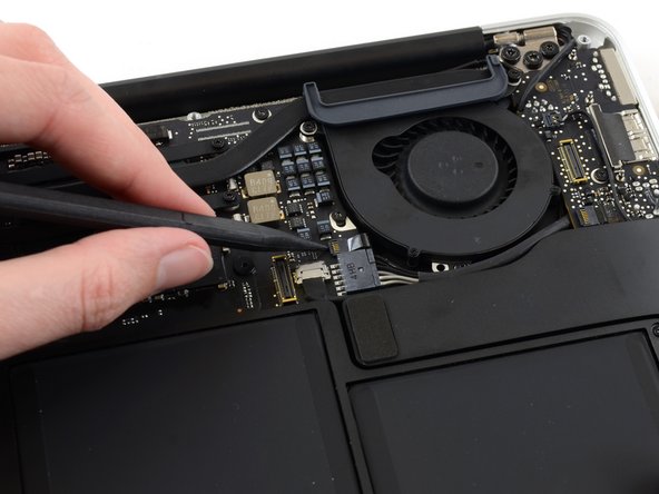
Use the tip of a spudger to carefully flip up the retaining flap on the fan cable ZIF socket.
The end of that cord slips into the channel whose lid you just flipped up. Don’t forget to re-insert that when reseating the fan and before flipping that retaining flap closed, it’s easy to miss and should have been part of these instructions, ifixit!
Thank you so much! Without your comment, I wouldn’t of realized that the ribbon cable is supposed to go into the socket (I know, dumb mistake now that I think about it). You also made me go back and correctly insert the microphone cable. Cheers!
After my repair, my fan is super loud now! Any tips?
I didn’t find any need to unplug the fan. All I did was remove the three screws which hold the fan to the case and gently fold the fan out of the way. All you are trying to do is gain enough room to route the camera cable into the little cut-out in the I/O board so it can go below the board along the edge of the fan.
I agree, BobY. I too didn't disconnect the fan cable. Those retaining flaps are so tiny it's hard even to see whether or not they are flipped up, so I was happy not to have to deal with it. That meant, however, that I had to be extra careful not to stress the fan cable when removing the fan (or more precisely, just lifting it out of the way rather than removing it completely), but I seem to have succeeded.
I wish I'd read these comments before unplugging that cable. I can't figure out how to reseat the cable so I can close the retaining flap. It would help if I could see it better, or had a better idea of how it was connected before I unplugged it.
-
-
-
-
Peel the rubber gasket off the adhesive on the top of the fan.
When putting the computer together, pay attention to the placement of the gasket. It has a pin on the left side the enters the main board from the bottom. The right side straddles the tip of the heat pipe and there is a photo later on with close-up.
-
-
-
Remove the following three screws securing the fan to the upper case:
-
One 5.2 mm T5 Torx screw
-
One 3.3 mm T5 Torx screw
-
One 4.4 mm T5 Torx screw with a short head
I was unable to remove the 4.4 mm screw with the T5. I needed to use the T4 to get a grip so I didn’t strip the head.
The 3.3mm Torx is actually a 4.4mm
-
-
-
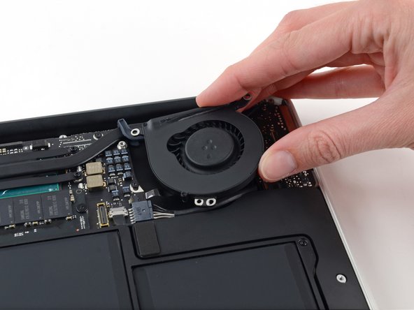
Lift the fan from the I/O board side and pull it free from the upper case.
-
Removing the fan will also disconnect the fan ribbon cable. Be careful not to snag it.
I didn’t find any need to remove the fan. I had no trouble routing the camera cable between the fan and the I/O board by just tilting the edge of the fan nearest the I/O board up and out of the way (pretty much what is being shown in the picture above).
I agree. I had to put something under the tilted (not removed) fan in order to have room to work, but it went okay.
I removed it but it was a little tricky getting the ribbon cable back in. I was afraid it would break but it finally seated after a little wiggling.
-
-
-
Disconnect the I/O board by pulling its power cable away from its socket on the logic board.
The connector has a latch (at least mine does) that prevents it from simply sliding out. To release it, I inserted a 5/64 flathead screwdriver to lift the edge of the socket. Then the jack and cable easily slides out.
-
-
-
Use the flat end of a spudger to pry the left speaker cable connector up and out of its socket on the I/O board.
when i did this the whole socket came off the board and i had to get a replacement i/o board. Be warned, do this very carefully and avoid my mistake
If you are here to replace the logic board, you can skip steps 12-16, they’re unnecessary to replace the logic board.
How do you put this back?? I’m struggling to figure out how to get the connector back into the socket of the new I/O board
You just line it up and push it down into the socket. Straight down, not sideways.
For Display disassembly you can skip this step.
I replaced a broken display of a MB Air with the functional of another MB Air. I removed the I/O board while disassembling the first Display, then I saw the comments so I tried it out while disassembling the second display. Worked out totally fine and saved me some time.
-
-
-
Use the tip of a spudger to carefully flip up the retaining flap on the microphone ribbon cable ZIF socket.
There was black tape covering this socket. It was attached to the ribbon tape. I needed to pull up the tape covering the socket to expose the retaining clip.
Thanks Brant!
The note about the black tape should be in RED in the main text above. I broke off the connector thinking the tape was part of the cable assembly. Always read the comments. Always. : )
Ripped the connector off the picture was too small and I couldn’t see what part to lift.
If you click on the picture, you'll get a nice detailed blown-up view.
-
-
-
Remove the single 4.1 mm T5 Torx screw securing the I/O board to the upper case.
Steps 14-15 & 28-29 seem unnecessary. I managed to replace the logic board without removing the I/O board or right speaker, although that means the logic board cannot be removed easily - the right rear corner is hindered by part of the chassis so that the edge of the logic board facing the battery should be lifted gently first and then the board be slid away from that obstructing part.
-
-
-
Gently de-route the camera cable from its notch on the I/O board and push it out of the way with the tip of a spudger.
This is really tricky. I couldn't de-route the cable as long as the I/O board was still in place. Had to lift the board mostly out of place in order to get enough slack in the cable to de-route it. Otherwise, I was going to have to force the de-routing, which seemed like a really bad idea.
-
-
-
Lift the I/O board from the logic board side and pull it free from the upper case.
-
Removing the I/O board will also disconnect the microphone ribbon cable. Be careful not to snag it.
Nor for the logic board removal
The back end of the microphone riibbon cable may be stuck down with a bit of glue under the flap. You can gently loosen it with a flat spudger.
how do I reattach the riibbon cable now that the adhesive has been removed?
I wonder if you weren't replacing the I/O board, BobY, but rather were doing some other repair. I say this because the microphone ribbon cable has to be disconnected from the I/O board in order to replace the I/O board, which is the repair that I was working on. And that disconnect/reconnect was definitely the fussiest part of this entire repair. Such tiny components to handle! In the end, I had to resort to using a tweezers, and even then I wasn't sure that everything was fully seated and secure.
I wasn't replacing the I/O Board, I was replacing the entire Display Assembly--I got to this step within the instructions for replacing the Display Assembly. Maybe iFixit uses the same comments if they link to this same step from a different set of repair instructions? My comment was meant to convey you definitely don't need to remove the I/O Board to replace the Display Assembly.
BobY -
I got to this point (Step 16) within the instructions for replacing the Display Assembly, which is where I'm entering this comment. My comment was meant to convey it isn't necessary to remove the I/O Board to replace the Display Assembly, but you certainly would need to remove the I/O Board to replace the I/O Board.
-
-
-
Remove the two 4.9 mm T8 Torx screws securing the antenna cable retainer on the left display hinge to the upper case.
-
-
Removing old thermal paste should be done carefully with a cotton swab and 100% isopropyl alcohol. Pure alcohol evaporates quickly, reducing the risk of residue. Applying thermal paste is kind of an art. You want to apply a single drop to square components, and a thin line to longer rectangular components. The thermal paste should be centered, so that it spreads out by itself, to cover the surfaces. Do not attempt to spread the paste by hand. Instead, let it spread out on its own, under the pressure of the heat sink. You can try watching a YouTube video to see how this is done.


To reassemble your device, follow these instructions in reverse order.
Take your e-waste to an R2 or e-Stewards certified recycler.
Repair didn’t go as planned? Try some basic troubleshooting, or ask our Answers community for help.
To reassemble your device, follow these instructions in reverse order.
Take your e-waste to an R2 or e-Stewards certified recycler.
Repair didn’t go as planned? Try some basic troubleshooting, or ask our Answers community for help.
Annulla: non ho completato questa guida.
Altre 19 persone hanno completato questa guida.


6 Commenti
My MAC didn’t have a gasket on the heat sink. It’s not about lazy, it’s about not finding that part. I assume the repair shop didn’t reassemble it correctly, or it came without.
The gasket is what is shown in step 8 that surrounds the long heatsink next to the backside of the case. It essentially wraps around the heatsink and rests on top of the small fan. The two purposes of this small gasket is primarily insulate the fan against vibration. The second function is that in some small part it could help provide insulating effects for air flow. This is to ensure that air passes through the fan and out of the rear of the heat exchanger and then out of the back of the laptop.
I suspect it for the first reason I gave primarily and really don’t see an issue as to the performance of the laptop. It just means it might be a little louder with rattle due to vibration.
Thanks for the guide C: i had the required tools. Mine is actually a 2017 but the 2015 one also works fine, got a mx4 and replace the thermal paste, now it dosent heat up at all. thanks
Pulling the fan cable out was terrifying but you actually just pull on the cable itself. No way to get any leverage at the connector to dislodge it. Did come out easily but like I said, scared me!
allison - Replica
Draai de schroefjes voorzichtig los en leg ze op een stabiele plek neer en let erop dat de schroefje een verschillende lengte hebben.
bwgvanderveer - Replica
I thought I could replace my 256 Gb SSD with 512? regards
ola m - Replica
Do you have good Test Point Voltages? It appears there are silver colored Test points on the I/O Board. I am working on a water spill and trying to troubleshoot if both the I/O board and the Logic need replaced.
andrew - Replica
It's probably not necessary but may be a little safer to completely discharge the old battery before replacing it.
Larry Smith - Replica
tell a model that was not inferior to the speed of the one in the laptop.
Thank you
ilyabuhov - Replica
Do i need to order tools separately to replace the battery i just ordered?
anne uhlir - Replica
im looking for a Logic Board for a
Apple - MacBook Air® - 13.3" Display - Intel Core i5 - 8GB Memory - 128GB Flash Storage (Latest Model) - Silver Model: MQD32LL/A
Any help is appreciated.
Jamie Comstock - Replica
P5 pentalobe screwdrivers are too big! The correct size for these screws are p4 pentalobe. P5 pentalobe was just able, with difficulty, to turn some of the screws. If the screws were at all tight, my p5 was unable to get them out, and started to strip the screws. A p4 screwdriver fit better and removed the screws with ease. (I was using high quality Wiha brand screwdrivers.)
William Skinner - Replica
I had same experience (with MacBook Air 13-inch Mid-2012) … had to get P4, which worked swimmingly
eric -
Very simple installation. The screwdriver heads were exactly what we’re needed, one head for the outside case screws, the other for the screws holding the battery in place. The computer started right up. Now to see how the battery holds up, but I have a good feeling about this!
Dennis Eaton - Replica
My P5 and the T5 worked perfectly with my early 2015 Air 13”! And it is super fast! Thank you iFixit!
Pennny Beach - Replica
The supplied kit and instructions worked perfectly!
Nikolay Andreev - Replica
Comments that the P5 pentalobe are too large are absolutely spot-on. There is no way the P5 pentalobe bit I have will work with the MacBook Air without destroying the screws. Hard target search for P4 pentalobe bit in progress…..
joemoog - Replica
Bonjour j’aimerais changer mon SSD de 128 Go pour en mettre un de 512 Go. Je ne sais pas ce qu’il faut prendre car il faut qu’il soit compatible avec le macbook air A1466. J’aurais vu un Samsung Evo 970 500 Go mais si je ne me trompe pas, il faut un adaptateur.
Merci pour votre aide.
chicco33 - Replica
oui, vous aurez besoin d’un adaptateur, pour completez le changement.
Dan -
The tool kit should include tweezers for re-inserting the battery connector.
Andre Clement - Replica
P5 pentalobe worked perfectly for me. Instructions were spot-on. Antenna connections were a bit fiddly to refit but got them in ok.
michaelquinnell - Replica
Maybe the problem some are experiencing is that the designations are confusing (blame Apple rather than iFixit). the P2 is also known as PL1. The P5 is also known as PL4. The P6 is also known as PL5. So it is possible to mistake the P6 (PL5) for the P5 (PL4), meaning it (P6-PL5) will be too big, while the P5 (PL4) will be just right. Sort of a 3 Bears explanation, but it is very confusing.
Thomas Lewis - Replica
To add to this. In searching for the P5 screwdriver to buy in UK, as far as I can tell, it is also known as
Pentalobe 1.2(mm)
also
P4 = 0.8
P6 = 1.5
Just unscrewed the back case of MacBook Air 13” mid 2011, with no problems using Pentalobe 1.2
nijafe -
I have not replaced a display on the A1369 but have done many A1466 which is a newer 13” model. They seem really similar and its not clear why one needs to remove the logic board to remove the display. The antenna cables on the A1466 dont have to rest under the logic board but can be tucked in the hinge crevice. Cant this same thing be done with the A1369?
Sean Love - Replica
Did mine today - but new battery wasnt charging. Went back in and noticed the battery connector cable was not quite 100% “seated. It was sticking out by less than a millimetre! - you need to give it quite a firm push in to get it seated properly. Otherwise - all ok .
John Brennand - Replica
Just installed on a MacBookAir6,2 (13-inch, Early 2014).
Was very easy.
New iFixit battery looks great so far:
Jonathan Cross - Replica
can you tell me which size of screwdrivers you’ve used to crack it up, please? I have the same model and size,
hawk_lpc -
Screw P5 Pentalobe 1.2
Mario Verlent - Replica
Install went flawlessly. Only challange was reattaching blue tooth antennas. Those sockets are so tiny.
Joel Sebastian - Replica
Installation was a little challenging at first because the instructions on this site did not perfectly match my model (late 2013 to early 2015).
Found this video on YouTube which described the procedure perfectly https://www.youtube.com/watch?v=Lue6lVWh...
Also the Ifixit kit I received was well put together with everything I needed and more. The calibration went perfectly and I am very pleased. Will buy again!!
Donald Niamath - Replica
Gently pulled out connector of old battery, then pressed and held the power switch for 1 minute. Unscrewed and removed the old battery. Pressed and held power switch for 1 minute again. I know from previous work that this helps drain charge from spontaneous recharging as the dielectric recovers. Gently “fine tuned” leads from new battery to connector till connector stuck out at right angle to the edge of battery. Held the battery by the edges and let the connector slide into the socket. Set the battery down and put the screws in all the way. Then checked that the connector was completely seated before tightening the screws. The laptop come on immediately and showed 98% charge and registered normal (checked in “About this Mac”. Very happy to this point. Now for calibration.
Amir Zaidi - Replica
Thank you very much for the guilde. My MBA2011 had reborn !
Billy Wong - Replica
Allow for electrostatics, otherwise you may cook components on the logicboard /motherboard (like I did with one of these!)
See great advice: Electrostatic Discharge
Fletcher Cole - Replica
… und wenn du eines von diesen wirklich kleinen Schräubchen vermisst: bevor du den Boden aufkehrst oder mit einem starken Magneten absuchst, schau mal am seitlichen (magnetischen) Ladekabelanschluss nach … ?
... and if you miss one of these really small screws: before you sweep the floor or search it with a strong magnet, take a look at the (magnetic) charging cable connection on the side … ?
Blatt - Replica
Fot All People ha ing trouble finding their SSD
DONT PRESS CMD +R + POWER
instead press
OPTION+CMD+R +POWER
I just installed Monterrey with WD black sn 770 SSD in m'y macbook air 2015
Albert - Replica
IFixit just had me submit "my story" re. fixing my MacBook Air 2013.
This repair was NOT difficult. The battery is enclosed in a plastic frame. It is NOT glued in like the newer models of Apple laptops. And unlike older laptops, the battery is not totally enclosed in a plastic housing. So once you remove the screws holding the batterie's frame, you can remove the battery.
Follow the instructions. Read the comments. Also read the comments re. installing a new battery.
Good luck. - Eric J.
ECJohansen - Replica
On the back of the laptop, notice that each screw is angled a little bit inward, aiming toward the middle of the laptop. Keep your screwdriver lined up with the screw (angled a bit outward as seen at 01:23 in the video: https://youtu.be/tToAwO6f-SY&t=83). This will help you get a good bite on the screw to get it out and avoid stripping the head of the screw.
Use the same angle when putting each screw back in. If the screw is in line with its hole it should not feel like you are fighting to screw it in. If it does, check your angle and back up a little; you should feel the screw fall into line.
Rich Garella - Replica
IFixit just had me submit "my story" re. fixing my MacBook Air 2013.
This repair was NOT difficult. The battery is enclosed in a plastic frame.
shrhh - Replica