Questa versione può contenere modifiche errate. Passa all'ultima istantanea verificata.
Cosa ti serve
-
CompraAttrezzo utilizzato in questo passaggio:P5 Pentalobe Screwdriver Retina MacBook Pro and Air$5.99
-
Svita le seguenti dieci viti:
-
Due viti Pentalobe 5-Point da 8 mm
-
Otto viti Pentalobe 5-Point da 2,5 mm
-
-
-
Usa la parte piatta di uno spudger per fare leva su entrambi i lati del connettore della batteria per scollegarlo dalla sua presa sulla scheda madre.
-
Piega leggermente il cavo della batteria lontano dalla scheda madre in modo che non torni a far contatto con la sua presa.
-
-
Questo passaggio è privo di traduzione. Aiuta a tradurlo
-
Use the flat end of a spudger to pry the left and right I/O board cable connectors up off their respective sockets on the I/O board.
-
-
Questo passaggio è privo di traduzione. Aiuta a tradurlo
-
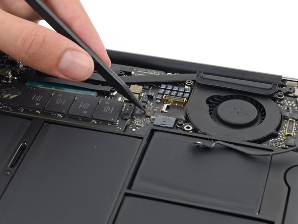
Use the tip of a spudger to carefully push on each side of the iSight camera cable connector to loosen it out of its socket on the logic board.
-
-
Questo passaggio è privo di traduzione. Aiuta a tradurlo
-
Peel the iSight camera cable up off the adhesive securing it to the fan.
-
-
Questo passaggio è privo di traduzione. Aiuta a tradurlo
-
Use the tip of a spudger to carefully flip up the retaining flap on the fan cable ZIF socket.
-
-
Questo passaggio è privo di traduzione. Aiuta a tradurlo
-
Remove the following three screws securing the fan to the upper case:
-
Two 5.5 mm T5 Torx screws
-
One 4.6 mm T5 Torx screw
-
-
Questo passaggio è privo di traduzione. Aiuta a tradurlo
-
Lift, but do not remove the fan out of its recess in the upper case.
-
Carefully pull the fan ribbon cable out of its socket as you remove the fan from the Air.
-
-
Questo passaggio è privo di traduzione. Aiuta a tradurlo
-
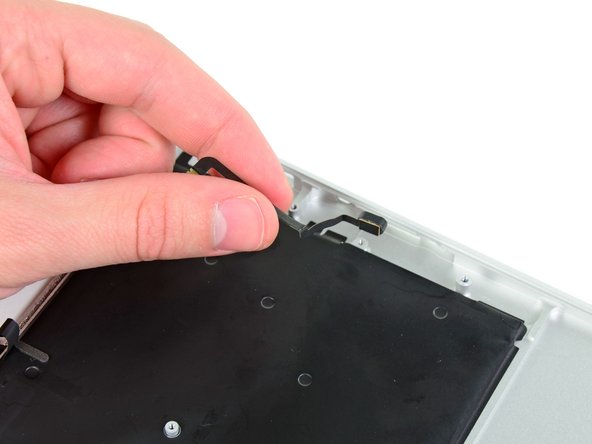
Use the flat end of a spudger to pry both antenna connectors up from their sockets on the AirPort/Bluetooth card, and move them out of the way.
-
-
Questo passaggio è privo di traduzione. Aiuta a tradurlo
-
Remove the following five screws securing the battery to the upper case:
-
Two 5.2 mm T5 Torx screws
-
One 6 mm T5 Torx screw
-
Two 2.6 mm T5 Torx screws
-
-
Questo passaggio è privo di traduzione. Aiuta a tradurlo
-
Lift the battery from its edge nearest the logic board and remove it from the upper case.
-
-
Questo passaggio è privo di traduzione. Aiuta a tradurlo
-
Disconnect the I/O board by pulling the power cable away from its socket on the logic board.
-
-
-
Questo passaggio è privo di traduzione. Aiuta a tradurlo
-
Use the tip of a spudger to de-route the antenna cables from their notches in the logic board.
-
-
Questo passaggio è privo di traduzione. Aiuta a tradurlo
-
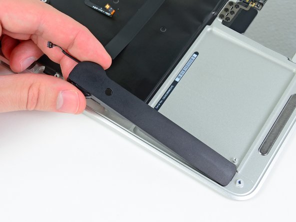
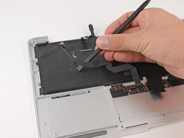
Gently push the tip of a spudger under the black plastic flap stuck to the display data cable lock to make the lock pop upward and away from the socket.
-
While holding the lock away from the socket, gently pull the display data cable out of its socket.
-
-
Questo passaggio è privo di traduzione. Aiuta a tradurlo
-
Use the tip of a spudger to pry under the speaker cable connector, lifting it straight up from its socket.
-
De-route the cable from its notch in the logic board.
-
-
Questo passaggio è privo di traduzione. Aiuta a tradurlo
-
Use the tip of a spudger or your fingernail to flip up the retaining flap on the trackpad ribbon cable ZIF socket.
-
Pull the trackpad ribbon cable straight out of its socket toward the front edge of the Air.
-
-
Questo passaggio è privo di traduzione. Aiuta a tradurlo
-
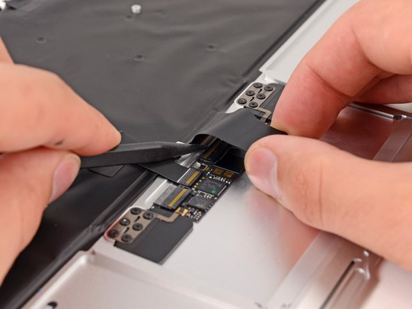
Use the tip of a spudger to flip up the retaining flap on the keyboard backlight ribbon cable ZIF socket.
-
Pull the keyboard backlight ribbon cable out of its socket.
-
-
Questo passaggio è privo di traduzione. Aiuta a tradurlo
-
Remove the single 2.9 mm T5 Torx screw securing the AirPort/Bluetooth card to the logic board.
-
-
Questo passaggio è privo di traduzione. Aiuta a tradurlo
-
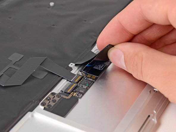
Slightly lift the free end of the AirPort/Bluetooth board and pull it out of its socket on the logic board.
-
-
Questo passaggio è privo di traduzione. Aiuta a tradurlo
-
Remove the three 3.6 mm T5 Torx screws securing the logic board to the upper case.
-
In some models these are 3.1 mm T5 Torx screws.
-
-
Questo passaggio è privo di traduzione. Aiuta a tradurlo
-
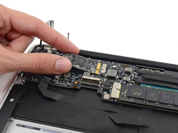
Gently lift the logic board assembly from the heat sink end and pull it away from the port side of the case to remove it from the Air.
-
-
Questo passaggio è privo di traduzione. Aiuta a tradurlo
-
Remove the small rubber gasket from the corner of the upper case nearest the the I/O board.
-
Remove the gasket from the corner nearest display cable connector.
-
-
Questo passaggio è privo di traduzione. Aiuta a tradurlo
-
Use the tip of a spudger to carefully flip up the retaining flap on the microphone cable ZIF socket.
-
With a pair of tweezers, pull the microphone ribbon cable straight out of its socket.
-
-
Questo passaggio è privo di traduzione. Aiuta a tradurlo
-
Use the tip of a spudger to pry under the speaker cable near the connector, lifting it straight up from its socket.
-
De-route the cable from its notch in the logic board.
-
-
Questo passaggio è privo di traduzione. Aiuta a tradurlo
-
Remove the single 3.6 mm T5 Torx screw securing the I/O board to the upper case.
-
-
Questo passaggio è privo di traduzione. Aiuta a tradurlo
-
Carefully lift the I/O board by its power cable and pull it away from the edge of the case.
-
-
Questo passaggio è privo di traduzione. Aiuta a tradurlo
-
Peel up the six cable loops securing the antenna cables to the upper case.
-
Gently pull the cable loops slightly out of the channel cut into the upper case one at a time.
-
Use your spudger to open up the plastic loops as you de-route the antenna cables through them.
-
-
Questo passaggio è privo di traduzione. Aiuta a tradurlo
-
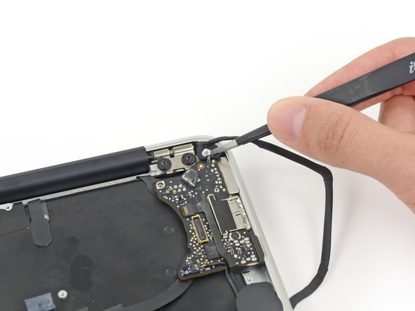
Remove the inner 4.9 mm T8 Torx screw securing each display hinge to the upper case (two screws total).
-
-
Questo passaggio è privo di traduzione. Aiuta a tradurlo
-
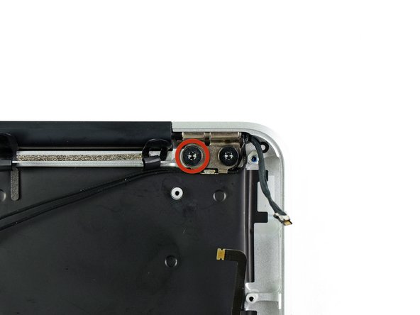
While holding the Air steady, remove the remaining 4.9 mm T8 Torx screw from the lower display bracket.
-
-
Questo passaggio è privo di traduzione. Aiuta a tradurlo
-
Remove the last 4.9 mm T8 Torx screw securing the display to the upper case.
-
-
Questo passaggio è privo di traduzione. Aiuta a tradurlo
-
Push the upper case slightly toward the display assembly, then rotate it away from the front of the display assembly.
-
Once the two display hinges have cleared the upper case, remove the display.
-
-
Questo passaggio è privo di traduzione. Aiuta a tradurlo
-
Use the flat end of a spudger to pry the right speaker off the adhesive securing it to the upper case.
-
Remove the right speaker from the upper case.
-
-
Questo passaggio è privo di traduzione. Aiuta a tradurlo
-
Use the flat end of a spudger to pry the left speaker off the adhesive securing it to the upper case.
-
Remove the left speaker from the upper case.
-
-
Questo passaggio è privo di traduzione. Aiuta a tradurlo
-
Use the tip of a spudger to pry the microphone away from the side of the upper case.
-
Remove the microphone from the upper case.
-
Upper case remains.
-
-
Questo passaggio è privo di traduzione. Aiuta a tradurlo
-
Push/lift the keyboard ribbon cable off of the upper case with one hand.
-
With the other hand, use a spudger to flip up the retaining flap on the ZIF connector.
-
Once the retaining flap has been flipped up, carefully pull the ribbon cable straight out of its socket.
-
-
Questo passaggio è privo di traduzione. Aiuta a tradurlo
-
Use the flat end of a spudger to separate the trackpad ribbon cable from the underside of the keyboard.
-
-
Questo passaggio è privo di traduzione. Aiuta a tradurlo
-
Remove the six 1.5 mm Phillips #00 screws securing the trackpad to the upper case.
-
Check your replacement upper case—if it doesn't have this wide T5 screw, remove it to transfer into the replacement.
-
-
Questo passaggio è privo di traduzione. Aiuta a tradurlo
-
Holding the upper case up off the table with one hand, gently push the trackpad up through the upper case.
-
Remove the trackpad from the upper case.
-


Annulla: non ho completato questa guida.
Altre 21 persone hanno completato questa guida.

