Questa versione può contenere modifiche errate. Passa all'ultima istantanea verificata.
Cosa ti serve
-
CompraAttrezzo utilizzato in questo passaggio:P5 Pentalobe Screwdriver Retina MacBook Pro and Air$5.99
-
Svita le seguenti dieci viti:
-
Due viti Pentalobe 5-Point da 8 mm
-
Otto viti Pentalobe 5-Point da 2,5 mm
-
-
-
Usa la parte piatta di uno spudger per fare leva su entrambi i lati corti del connettore della batteria per scollegarlo dalla sua presa sulla scheda madre.
-
Piega il cavo della batteria lontano dalla scheda madre in modo che non faccia contatto accidentalmente con la sua presa.
-
-
Questo passaggio è privo di traduzione. Aiuta a tradurlo
-
Use the flat end of a spudger to pry the I/O board cable up from its socket on the I/O board.
-
-
Questo passaggio è privo di traduzione. Aiuta a tradurlo
-
Peel the I/O board cable up from the adhesive securing it to the fan.
-
-
-
Questo passaggio è privo di traduzione. Aiuta a tradurlo
-
Use the flat end of a spudger to lift the I/O board connector up and out of its socket on the logic board
-
Remove the I/O board cable.
-
-
Questo passaggio è privo di traduzione. Aiuta a tradurlo
-
Use the tip of a spudger to carefully flip up the retaining flap on the fan cable ZIF socket.
-
-
Questo passaggio è privo di traduzione. Aiuta a tradurlo
-
Remove the following three screws securing the fan to the upper case:
-
Two 5.2 mm T5 Torx screws
-
One 3.6 mm T5 Torx screw
-
-
Questo passaggio è privo di traduzione. Aiuta a tradurlo
-
Lift the fan out of the upper case and carefully pull the fan ribbon cable out of its socket as you remove it from the Air.
-
-
Questo passaggio è privo di traduzione. Aiuta a tradurlo
-
Remove the following five screws securing the battery to the upper case:
-
Two 5.2 mm T5 Torx screws
-
One 6 mm T5 Torx screw
-
Two 2.6 mm T5 Torx screws
-
-
Questo passaggio è privo di traduzione. Aiuta a tradurlo
-
Lift the battery from its edge nearest the logic board and remove it from the upper case.
-
-
Questo passaggio è privo di traduzione. Aiuta a tradurlo
-
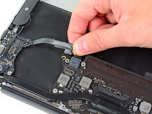
Disconnect the I/O board by pulling the power cable away from its socket on the logic board.
-
-
Questo passaggio è privo di traduzione. Aiuta a tradurlo
-
Use the tip of a spudger to carefully flip up the retaining flap on the microphone cable ZIF socket.
-
Pull the microphone ribbon cable straight out of its socket.
-
-
Questo passaggio è privo di traduzione. Aiuta a tradurlo
-
Use the flat end of a spudger to pry the left speaker cable connector up and out of its socket on the I/O board.
-
-
Questo passaggio è privo di traduzione. Aiuta a tradurlo
-
Pull the camera cable parallel to the face of the I/O board toward the rear edge of the Air to disconnect it from its socket.
-
-
Questo passaggio è privo di traduzione. Aiuta a tradurlo
-
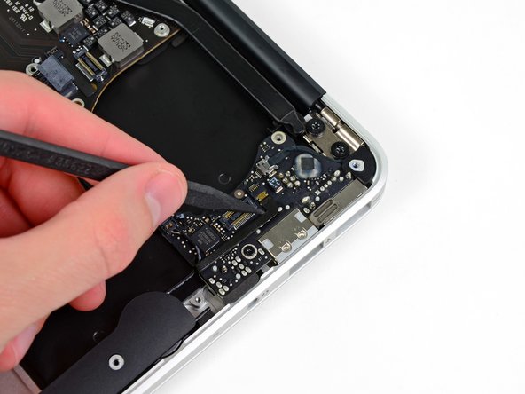
Remove the small rubber gasket from the corner of the upper case nearest the I/O board.
-
-
Questo passaggio è privo di traduzione. Aiuta a tradurlo
-
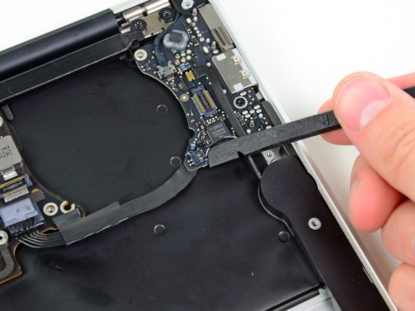
Remove the single 3.6 mm T5 Torx screw securing the I/O board to the upper case.
-
-
Questo passaggio è privo di traduzione. Aiuta a tradurlo
-
Carefully lift the I/O board from its edge nearest the logic board and remove it from the upper case.
-


Annulla: non ho completato questa guida.
Altre 42 persone hanno completato questa guida.

5 Commenti
Thanks. Great instructions!
Thank you so much. Just replaced my IO board and the whole process went without a hitch. I’m absolutely thrilled now that I can charge my Air without going through an extensive wriggling routine with the MagSafe connector every time.
Good day! As I can see it’s all the same with Air 2012 logic board…
I’m looking the board to replace my 2GB mid 2011, can I take 4GB mid 2012 with 1.7Ghz ..?
This was exactly what I needed!!! I replaced the I/O board and I/O board cable on a macbook 11” A1465 that was not charging or playing sound. It now works. Great explanations and details.
Thanks. Good instructions.