Questa versione può contenere modifiche errate. Passa all'ultima istantanea verificata.
Cosa ti serve
-
CompraAttrezzo utilizzato in questo passaggio:P5 Pentalobe Screwdriver Retina MacBook Pro and Air$5.99
-
Svita le seguenti dieci viti:
-
Due viti pentalobe da 8 mm
-
Otto viti pentalobe da 2,5 mm
-
-
Questo passaggio è privo di traduzione. Aiuta a tradurlo
-
Use the flat end of a spudger to pry both short sides of the battery connector upward to disconnect it from its socket on the logic board.
-
Bend the battery cable slightly away from the logic board so the connector will not accidentally contact its socket.
-
-
Questo passaggio è privo di traduzione. Aiuta a tradurlo
-
Remove the single 2.9 mm T5 Torx screw securing the SSD to the logic board.
-
-
Questo passaggio è privo di traduzione. Aiuta a tradurlo
-
Use a spudger to help lift the free end of the SSD just enough to grab it with your other hand.
-
Pull the drive straight out of its socket and remove it from the logic board.
-
-
Questo passaggio è privo di traduzione. Aiuta a tradurlo
-
Use the flat end of a spudger to pry the I/O board cable connector upward out of its socket on the I/O board.
-
-
Questo passaggio è privo di traduzione. Aiuta a tradurlo
-
While gently pulling the I/O board cable upward near its connection to the logic board, use the tip of a spudger to pry upward on alternating sides of the connector to help "walk" it out of its socket.
-
Remove the I/O board cable.
-
-
Questo passaggio è privo di traduzione. Aiuta a tradurlo
-
Use the tip of a spudger to carefully flip up the retaining flap on the fan cable ZIF socket.
-
-
Questo passaggio è privo di traduzione. Aiuta a tradurlo
-
Remove the following three screws securing the fan to the upper case:
-
Two 5.2 mm T5 Torx screws
-
One 3.6 mm T5 Torx screw
-
-
Questo passaggio è privo di traduzione. Aiuta a tradurlo
-
Lift the fan out of the upper case and carefully pull the fan ribbon cable out of its socket as you remove it from the Air.
-
-
-
Questo passaggio è privo di traduzione. Aiuta a tradurlo
-
Remove the following five screws securing the battery to the upper case:
-
Two 5.2 mm T5 Torx screws
-
One 6 mm T5 Torx screw
-
Two 2.6 mm T5 Torx screws
-
-
Questo passaggio è privo di traduzione. Aiuta a tradurlo
-
Lift the battery from its edge nearest the logic board and remove it from the upper case.
-
-
Questo passaggio è privo di traduzione. Aiuta a tradurlo
-
Disconnect the I/O board by pulling the power cable away from its socket on the logic board.
-
-
Questo passaggio è privo di traduzione. Aiuta a tradurlo
-
Use the tip of a spudger or your fingernail to flip up the retaining flap on the trackpad ribbon cable ZIF socket.
-
Pull the trackpad ribbon cable straight out of its socket toward the front edge of the Air.
-
-
Questo passaggio è privo di traduzione. Aiuta a tradurlo
-
Use the tip of a spudger to de-route the right speaker cable from the slot cut into the logic board.
-
-
Questo passaggio è privo di traduzione. Aiuta a tradurlo
-
Use the flat end of a spudger to pry the right speaker cable connector up and out of its socket on the logic board.
-
-
Questo passaggio è privo di traduzione. Aiuta a tradurlo
-
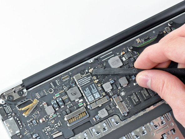
Gently push the tip of a spudger under the black plastic flap stuck to the display data cable lock to make the lock pop upward and away from the socket.
-
While holding the lock away from the socket, use the tip of a spudger and your fingers to gently remove the display data cable from its socket.
-
-
Questo passaggio è privo di traduzione. Aiuta a tradurlo
-
Remove the small rubber gasket from the corner of the upper case near the display data cable.
-
-
Questo passaggio è privo di traduzione. Aiuta a tradurlo
-
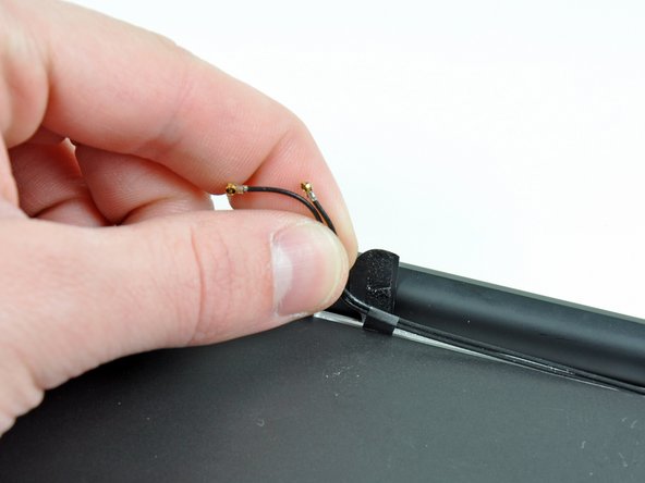
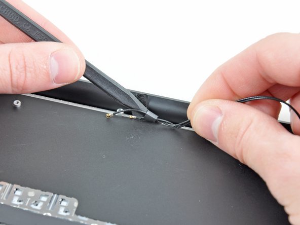
Use the flat end of a spudger to pry both antenna cable connectors up and off their sockets on the AirPort/Bluetooth card.
-
-
Questo passaggio è privo di traduzione. Aiuta a tradurlo
-
Gently de-route the antenna cables from the slot cut into the logic board.
-
-
Questo passaggio è privo di traduzione. Aiuta a tradurlo
-
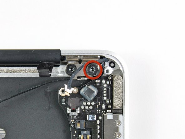
Remove the three 3.6 mm T5 Torx screws securing the logic board to the upper case.
-
-
Questo passaggio è privo di traduzione. Aiuta a tradurlo
-
Gently lift the logic board assembly out of the upper case, minding the fragile heat sink and any cables that may get caught.
-
-
Questo passaggio è privo di traduzione. Aiuta a tradurlo
-
Pull the camera cable parallel to the face of the I/O board toward the rear edge of the Air to disconnect it from its socket.
-
-
Questo passaggio è privo di traduzione. Aiuta a tradurlo
-
Remove the small rubber gasket from the corner of the upper case nearest the I/O board.
-
-
Questo passaggio è privo di traduzione. Aiuta a tradurlo
-
Peel up the six cable loops securing the antenna cables to the upper case.
-
Gently pull the cable loops slightly out of the channel cut into the upper case one at a time.
-
Use your spudger to open up the plastic loops as you de-route the antenna cables through them.
-
Repeat this for all five retaining loops.
-
-
Questo passaggio è privo di traduzione. Aiuta a tradurlo
-
Remove the outer 4.9 mm T8 Torx screw securing each display hinge to the upper case (two screws total).
-
-
Questo passaggio è privo di traduzione. Aiuta a tradurlo
-
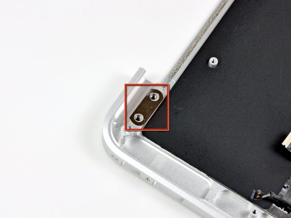
Open the display until it is perpendicular to the upper case and place it on a table as shown.
-
While holding the Air steady, remove the remaining 4.9 mm T8 Torx screw from the lower display bracket.
-
-
Questo passaggio è privo di traduzione. Aiuta a tradurlo
-
Remove the last 4.9 mm T8 Torx screw securing the display to the upper case.
-
-
Questo passaggio è privo di traduzione. Aiuta a tradurlo
-
Push the upper case slightly toward the display assembly, then rotate it away from the front of the display assembly.
-
Once the two display hinges have cleared the upper case, remove the display and set it aside.
-


Annulla: non ho completato questa guida.
Altre 45 persone hanno completato questa guida.

3 Commenti
Can I change the flex cable... the display cable in a macbook air? Or I have to change all the display? thank
You can change it, but you have to buy the cable with the hinge and change both because it goes together.
One of the antenna cables got stuck in one of the loops, so I pulled it and the antenna connector got off. Now I can’t connect to the Internet. And there is no easy or cheap fix for this problem. So, people, be careful. Better to cut open some of the loops around antenna cables than make my mistake.