Questa versione può contenere modifiche errate. Passa all'ultima istantanea verificata.
Cosa ti serve
-
Questo passaggio è privo di traduzione. Aiuta a tradurlo
-
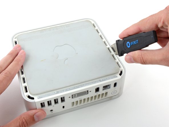
Power down your Mac mini, disconnect all of the cables, and flip it over.
-
Insert the Jimmy into the crack between the aluminum top housing and the plastic lower housing.
-
The Jimmy should reach a stop about 3/8" down.
-
-
Questo passaggio è privo di traduzione. Aiuta a tradurlo
-
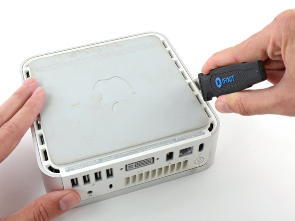
Gently bend the Jimmy outwards to pry the crack open a little larger and lift the lower housing up a small amount.
-
-
Questo passaggio è privo di traduzione. Aiuta a tradurlo
-
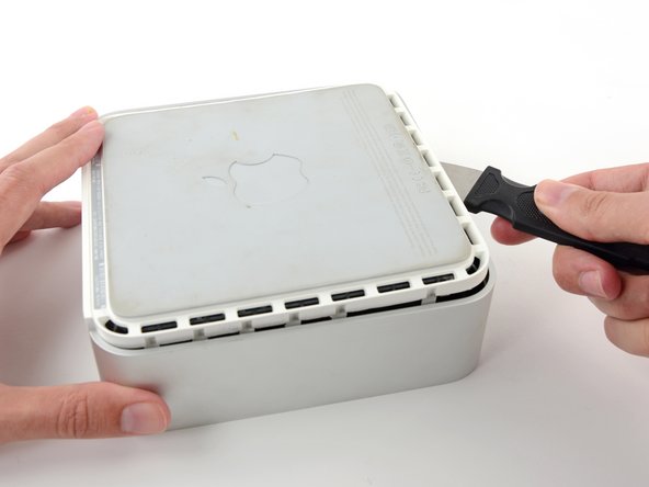
Once you have the first side free, rotate the Mac mini and start prying up on the front edge.
-
Use the same prying motion to both bend the clips inward and lift the lower housing up out of the top housing.
-
-
Questo passaggio è privo di traduzione. Aiuta a tradurlo
-
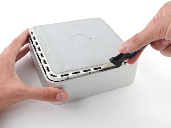
You may need to move the Jimmy along the edge to pry up all of the clips. Be patient and do a little bit at a time.
-
-
Questo passaggio è privo di traduzione. Aiuta a tradurlo
-
Keep working around the perimeter, freeing the clips along the final edge.
-
-
Questo passaggio è privo di traduzione. Aiuta a tradurlo
-
Flip the Mac mini back over and lift the top housing off of the lower housing.
-
-
Questo passaggio è privo di traduzione. Aiuta a tradurlo
-
We will first remove the AirPort antenna, located in the lower left corner of this picture.
-
-
Questo passaggio è privo di traduzione. Aiuta a tradurlo
-
Slightly squeeze the two retaining arms toward each other and lift the AirPort antenna off its post.
-
-
-
Questo passaggio è privo di traduzione. Aiuta a tradurlo
-
Grab the Bluetooth antenna nearest the port side of the computer by the edges of the board and pull it straight up off the internal frame.
-
-
Questo passaggio è privo di traduzione. Aiuta a tradurlo
-
Remove the antenna board near the front of the mini by pulling it straight up off the internal frame.
-
If necessary, remove the piece of tape securing the antenna leads to the internal frame.
-
-
Questo passaggio è privo di traduzione. Aiuta a tradurlo
-
Use the flat end of a spudger to pry the audio ribbon cable connector up off the audio board.
-
-
Questo passaggio è privo di traduzione. Aiuta a tradurlo
-
Remove the following four screws securing the internal frame to the bottom housing:
-
Three 6.7 mm Phillips #00 screws
-
One 9.5 mm Phillips #00 screw
-
-
Questo passaggio è privo di traduzione. Aiuta a tradurlo
-
Lift the internal frame off the bottom housing, starting at the rear edge, until you feel the concealed edge connector on the motherboard disconnect. Then lift straight off, minding the bluetooth and 802.11 antenna cables.
-
-
Questo passaggio è privo di traduzione. Aiuta a tradurlo
-
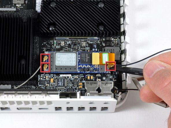
Use the flat end of a spudger to pry the three antenna connectors off the AirPort/Bluetooth combo card.
-
-
Questo passaggio è privo di traduzione. Aiuta a tradurlo
-
Use the flat end of a spudger to pry the AirPort/Bluetooth ribbon cable connector up off the combo card.
-
-
Questo passaggio è privo di traduzione. Aiuta a tradurlo
-
Remove the three silver Phillips screws securing the combo card to the logic board.
-
Lift the combo card out of your mini.
-
-
Questo passaggio è privo di traduzione. Aiuta a tradurlo
-
Use the flat end of a spudger to pry the power button cable connector up off the logic board.
-
-
Questo passaggio è privo di traduzione. Aiuta a tradurlo
-
Use the flat end of a spudger to pry the sleep light cable connector up off the logic board.
-
-
Questo passaggio è privo di traduzione. Aiuta a tradurlo
-
Remove the single T10 Torx lug next to the RAM sockets on the logic board.
-
-
Questo passaggio è privo di traduzione. Aiuta a tradurlo
-
Use a spudger to lift the free end of the logic board off the bottom housing near the PRAM battery.
-
-
Questo passaggio è privo di traduzione. Aiuta a tradurlo
-
While slightly lifting the free end of the board pull it away from the port side of the mini, minding any edges that may get caught.
-
-
Questo passaggio è privo di traduzione. Aiuta a tradurlo
-
Remove the single Phillips screw between the headphone and microphone jacks on the audio board.
-
-
Questo passaggio è privo di traduzione. Aiuta a tradurlo
-
Lift the audio board by its free edge and pull it away from the port side of the mini.
-


Annulla: non ho completato questa guida.
Altre 3 persone hanno completato questa guida.
