Introduzione
Guida solo prerequisita.
Cosa ti serve
-
-
Rimuovi la vite Torx T6 da 2,6 mm che fissa la staffa del connettore del cavo SATA.
-
-
-
Rimuovi la staffa del connettore del cavo SATA.
This procedure works to add a SATA hard drive/SSD to a PCIe SSD-only Mac Mini using iFixit's Mac Mini Dual Drive Kit. The one thing that's missing from the kit is SATA cable connector bracket (and screw). This is not the end of the world: the cable is a snug fit in the logic board socket, so the bracket is only a safety measure.
Its shown in the 2nd picture but is very easy to skip over and I almost lost mine because I did exactly that. While I thing the connector would stay without it The little cover that hold the connector down would be a bad thing to have floating around in the machine.
-
-
-
Utilizza l'estremità piatta di uno spudger per sollevare il connettore del cavo SATA dal suo alloggiamento sulla scheda logica.
Last time I did this I got the tool under the socket and it broke off. This caused the power light not to work. I don’t use the IR function so it wasn’t an issue. When putting this connector back on, make sure it seats well as many have has issues with the the power light not working. You will read more of this on the comments at the bottom
-
-
-
Utilizza la punta di uno spudger per scollegare il connettore del cavo del sensore IR facendo leva direttamente dal suo alloggiamento.
Be careful in this step. I am known for my gentle hands and the little cable flew out regardless. Was able to reinsert with no damage but was terrifying!
What if the entire connector came off? Can this be glued again? How can I fix this?? :(
@caicruzz The socket will have to be re-soldered to the board. It’s not terribly difficult, but requires some specialized equipment and I wouldn’t recommend it as a DIY on any machine you care about, at least not without a lot of practice first. I’d suggest reaching out to a repair shop that handles board-level repairs. Sorry for the frustration! Accidents happen sometimes; fortunately this one is very fixable.
This happened to me as well. Can I simply tape it in place? I’m never going to use the IR sensor anyway.
Is you made mini working without connecting the Broken IR bracket? I did this the other day and I can live without the IR and LED light. I could solder it, but rather not if the machine works without it
I did this. So mad at myself. Will my Mini still work if I left it as is. I understand that I won’t have IR and the LED light won’t work, but I can live without it
I broke it too. Really annoying as I do use (or, used to) the IR sensor).
Je l’ai cassé aussi ….
I would recommend to go on till step 24, till the motherboard is pulled out slightly, then come back to this step. The space is very tight between the connector and the hard disk bracket, which makes it difficult to slide the spudger underneath the wires. It is much easier when the motherboard is slightly out and have more space for the tool. I followed @juggledad’s comment, and used a pair of fine tip tweezers to pry the connector out.
Capteur cassé; comme vous autres
You may also use a bowed paper clip and slide it under all wires and gently pry it open
Because of the warnings in the comments I decided to use another tool. Instead of using a spudger, I carefully used the Flathead 1 bit from the iFixit Mako precision bit set in this step. That worked well for me.
YES! I followed recommendation to go on till step 24, as Xu Yang suggested. Worked easy for me. Thank you all!!!
I moved the mainboard too far away and the cables came out of the connector, without damage (whew). In this situation, when putting back the pins in the connector, remember that the pinout is plain simple: referring to the other end of the cable the order is pin-to-pin (1 to 1, 2 to 2, etc.).
-
-
-
-
I seguenti tre passaggi si applicano solo ai Mac mini dotati di SSD PCIe. Salta i prossimi tre passaggi se il tuo Mac mini ha un normale disco rigido.
-
Rimuovi le due viti T6 da 2,6 mm che fissano la staffa del cavo SSD PCIe.
Steps 18-20 only apply if you are removing a fusion drive. Otherwise skip to step 21 during removal.
-
-
-
Solleva il connettore SSD PCIe dal suo alloggiamento.
Is the PCIe connector present and usable on the mid-range Mac mini? I don't need the ~$300 fusion drive but would like the comfort of knowing that I can add an extra SSD in the future.
Not true. I am looking @ the inside of a mac mini _not_ configured with a fusion drive, and the connector is present.
The PCIe connector is only present if the computer came factory configured with any sort of flash storage (SSD or fusion drive). Otherwise, the cable, the connector, the bracket, and the 2 screws are all missing. The fusion drive is essentially a disk drive plus a small capacity SSD blade which the OS recognizes as a combined drive. Fortunately, if you didn’t have an SSD before, you can easily buy the connector cable part on the internet. The bracket and screws are not necessary.
Is it correct that the “iFixit Mac mini Unibody SSD Upgrade Bundle” with a 500-Gbyte Crucial MX500 SSD does not require a PCIe connector? This is for a late 2014 Mac Mini with a failed HDD (order number MGEM2*/A). I think it is correct, as the connectors on the Crucial SSD look just like those on the HDD, but just checking…
-
-
-
Rimuovi la singola vite Torx T6 da 16 mm che fissa la scheda logica.
-
-
-
Inserisci lo strumento di rimozione della scheda logica Mac mini nei due fori evidenziati in rosso. Assicurati che le aste entrino in contatto con la custodia sotto la scheda logica prima di procedere.
Instead of the removal tool it is also possible to use two metal pins with 2,5mm diameter.
Yes - You need a T8 there rather than T9.
T9 was a perfect fit for me.
dloftis -
You don’t need a tool for this step, just turn the Mac Mini around 180º and push the vent for the fan with your thumbs. The board will push straight out. That’s what I did.
Sure, nice tip - it works for me fine - thks for it :D
Tom
Nice tip, thx
Mats -
Simple thumb-pushing didn’t work for me, so I bought the tool.
Insert the MMLBRtool. How far? There’s an initial lip you might catch about halfway down, but wiggle beyond the lip to a definite bottoming out, and equal lengths of the tool on each side of the elbows as shown.
As you lever the logic board per the illustrations, you’ll notice the black bezel begin to separate on one side or the other. Use a prying tool or guitar pick to help separate the bezel from the body on top and bottom, and the logic board will slide out easily with gentle prying.
On my Mini, the bezel’s retaining clips (best seen in Step 25) were very snug to the body, preventing the thumb-push. Using the pick released them from the body.
You definitely don’t need the tool. Just get two screwdrivers small enough to fit in the holes and push them both at the same time. I have about a million tiny torx screwdirvers that came with iphone screen replacement kits. I’m sure you do too.
This is exactly what I used, thanks for the tip. Worked a charm once I leveraged both small screwdrivers back with even pressure just like you can with the removal tool.
Ahmad -
I used an old coat hanger. I just cut the end off with some pliers and then bent it into a similar shape as the tool. The biggest thing is making sure both sides are about the same length. Also, don’t put your thumbs on the black plastic part on the back of the mini because you won’t be able to pull the logic board out that way.
I used 2 screw drivers as suggested, and pulled towards me with my palms against the sides of the case. Even with a lot of muscle, I failed. The solution was to get a helper on the opposite side of the table. Using the fingers of both hands along the circular opening in the case, the helper pulled as I pulled on the screwdrivers. They should be kept vertical, so as to not damage the board. There is no way the procedure pictured in step 23 would have worked for me. My board must have needed at least 20 pounds of force to move
Totally didn’t need to buy the tool they recommended. Just use two tiny screwdrivers (the same ones you are already using to take apart your mac. Pull at the same time toward you and the whole board popped out in a few seconds.
etape la plus délicate du tuto, j’ai pour ma part fait levier avec la partie plate de la spatule en plastique entre le berceau du disque dur et la carte mère juste à coté du connecteur ir, la facade s’est légerement décollée, j’ai changé de place toujours avec la même méthode et la facade a continué de sortir, j’ai ensuite pu aider avec les trous initialement prévus (j’ai utilisé 2 tournevis torx très fin) et ensuite c’est sorti sans souci
I had the tool and it worked perfectly. However, it did not push easily out. It came out hard and nearly went flying. Luckily nothing was damaged but just FYI, mine was super tight.
You totally don’t need the one-use-only “logic board removal tool”, that’s silly. If you push against the heatsink with both thumbs (being careful not to make the board flex) and wiggle it out it’ll eventually give and slide out.
-
-
-
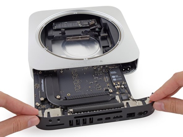
Tira con cautela lo strumento verso la scheda di interfaccia. La scheda logica e la scheda di interfaccia devono essere leggermente sfilati dalla custodia esterna.
-
Smetti di tirare quando lo strumento di rimozione entra in contatto con l'apertura posteriore della carcassa.
I had some trouble getting mine started here. If your logic board seems stuck, try pushing the removal tool on both sides near the bottom (vs the top like the photos show) with your index fingers, holding the case with your ring and pinky fingers so that your hands are completely free of the back of the computer (the side with the ports). This worked for me. Otherwise, this guide made the process smooth!
I had the same issue until I read this comment. Worked as explained. Thanks !!
The removal tool fits into sockets below the board, just 'lean' the tool over and the logic board will ease out. When refitting the logic board make sure the tabs around the I/O shield slip inside the shell and press home firmly. If the fixing screw does not thread into it's hole, the board is not fully home.
This is what worked for me!
Make sure you do *not* have your thumbs on the black plastic I/O shield while attempting this step!
I was able to push the logic board out, with a little bit of stress and patience, without the specified tool. Rather I used two paper clips, larger than average, and being very gentle to get the initial nudge. I then finished it off using only my fingers, as the paper clips were not strong enough and would have bended. Doable, but probably easier with the tool.
Even with the tool - it takes more force than you think. There are clips on both sides of the board. Be aware of that when putting it back.
I used 2 mini flathead screwdrivers with the same thickness as the holes with the heads aligned straight up and down. They will fit into little sockets attached to the case below the board. The side with the power cord came out much easier than the side with the headphone jack, so I removed the tools after a small gap was created and pushed semi-hard on the logic board with a broken spudger (a screwdriver would have worked, too) right in the elbow curve shown to the left of the screw in step 14, and the whole thing slid right out.
I saw a video where a guy just used a coat hanger to make his own tool. Good to know in case you've already started taking it apart and haven't already purchased the tool. https://www.youtube.com/watch?v=hgEBPlz4...
The coat hanger trick worked flawlessly for me. Very easy.
Jochen -
May be its me, but I had a right issue with this, I then noticed the screw I loosened in step 10 was bending over. I removed the screw completely, logic board came out, and the metal pillar on the underneath of the board where said screw went in was bent. When I put it all back together afterwards after changing the drive, that long screw was bend, on straightening everything up, the pillar snapped off the logic board. Everything tightened up and its booted up fine. It might just me not following the instructions properly though
Same here. The screw has to be backed out further than I thought. This should maybe be clearer.
For me the screw loosened in step 10 came out with the fan. it "should" be a captive screw meaning it doesn't stay in when the fan comes out
I had 2 complete sets of allen wrenches, one metric and one standard and found one each that fit the holes perfectly. With those I was able to find the "pry spots" that are on the base of the case very easily and a slight nudge moved the board. really worked EXCELLENTLY
My logic board was hung up on the left side with the plastic retainer or the two grounding tabs not giving up the ghost. There is no good picture of this on this procedure. If you go the the heat sink replacement procedure you can see a pretty good bit of it below the presenter’s right thumb in the opening pic and in a larger pic at step 27. Not that the logic board assembly can move much while seated I was able to shift (ever so slightly) the black plastic backside to the right and the board finally unlatched and came out. I was so worried that I was going to over force it and break something, you know, like the logic board. Not sure if I have a solution other than don’t force it. If it seems hard and one side seems to have a screw or other some such locking device stop forcing it and try shifting the logic board to the side opposite were it is catching.
I had an issue during reassembly where the AC in socket was just offset and would not line up correctly. I inserted the power cord (unplugged from wall) as I did the final push and everything finally lined up right.
One thing about sliding the assembly board in, i.e. when you are doing the steps backwards, is that there is squishy pad on left and clip on the righ (when viewing mac mini from bottom) if you carefully observe and then it becomes easy to get the assembly in or out if you think about it.
Though I’m sure the tool would work really well, we were able to trouble shoot this with an old microwave oven tray. We clipped the pieces and they were strong and small enough to help remove the logic tray.
This step seems like it would be easier with a lot of thin tools like iFixit’s Jimmy being used to release the clips holding the IO panel to the case. It will slide apart with brute force, but until you realize what’s holding it shut, it feels like more force than it reasonable.
No clips or screwdrivers. I used my barehands over the air tunnels, that was very quick.
I’m not sure how safe it is but worked just fine for me.
This was very daunting going in (I had flashbacks of iPhone 4 screen replacements), but turned out to be mostly a breeze. Despite the amount of steps everything inside is very modular and fastened with a minimum number of screws. Logic board module slid right out with very slight pressure on the air vents. Most difficult part was getting the DC connector out and the side clips of the logic board module back in. Much to my surprise, I had it all done in 25 mins. Excellent guide.
I used a single mini/ Jewelers philips screw driver #0 that fit perfectly into the hole and he socket at the base. A gentle “lean in” on each hole loosened the board, ready to slide out.
After some head scratching I found you don't want to insert the removal tool too deep. If you do you wont be able to slide the board out.
I followed the advice of a pro, put the machine on the floor and my knees to the back end corners. From there I could push with screwdrivers down the holes and it loosened.
-
-
-
Estrai il connettore del cavo DC-In dal suo alloggiamento sulla scheda logica.
When reassembling, I made the mistake of pushing the logic board all the way in before trying to reattach the DC-In cable connector. It is much easier to reattach the connector with the logic board pushed in just short of final seating.
Very usefull comment!!!
Excellent tip, thank you! I would suggest to @sam that this tip be added to the main steps so that others are more likely to see it. Saved me a lot of potential difficulty!
very small needle-nose pliers help, when reassembling.
This is very tricky and to get it off requires a fair bit of (considered) force. Putting it back on I also found a little difficult until I realized it seats slightly lower than you might anticipate. The connector isn’t flush with the top of the motherboard.
I was going to make this comment too. I spent 10 minutes trying to plug it in. It sits much lower than I expected too.
Use some tweezers to help work out each side as you pull with your fingers.
I pushed down on all the wires against the black plastic frame beneath to secure the wires tight. This allows you to then pull the logic board from the front until the connector pops out.
Pour faciliter l’extraction de cette nappe de fil j’ai fait une boucle autour de celle-ci avec un lien fait d’une fine bande de plastique noir muni en son centre d’un petit fil de cuivre pour la solidité, on trouve ce genre de liens au moment du déballage de matériel électronique ou ils servent à tenir les câbles enroulés dans de petit sacs plastique. Une fois enroulé autour de la nappe il suffit de tirer sur cette attache ce qui permet de tirer sur tout les fils de la nappe en même temps et ainsi d’éviter de tirer uniquement sur quelques fils.
Thanks for a thorough guide, except for one point -
the Hard Drive connector landing point on the Logic Board. I did not notice how the connector came off when I pulled the Logic Board.
Please add a circle around that connector on the logic board, AND how to get it re-installed. I ended up ripping the tiny gold "connections" off of a logic board when trying to get the Hard Drive cable re-seated.
-
-
-
Fai scivolare delicatamente il gruppo della scheda logica del Mac mini, facendo attenzione a eventuali cavi che potrebbero impigliarsi.
If you can’t get the logic board assembly back in so that it is flush (as it was before you did your surgery on the machine) then I would pay attention to two things: 1) the “sock.” Make sure it is back in place in the right way. I wish I could tell you which way that is but because there is no picture I had to guess and I can’t remember what my guess was now. 2) the retaining clip in step 26. I was unable to properly seat the logic board back into the machine so that it was flush UNTIL I fooled around with the clip and, I GUESS, put it in properly this time. After I did that I was able to properly push the logic board back into place.
Unless it was seated perfectly when the machine was first put together, the “sock” is likely to come off the logic board assembly when you pop the logic board out. To help reassemble, I have this advice:
1. The sock has two parts, a stiffer rectangle part and a softer oval part with ridges. The oval part goes towards the outside (back) of the board assembly (where all the receptacles are for the external connections); the rectangle goes towards the inside of the machine.
2. The rectangle has a stiff, rectangular “magnet-like” piece on one side: that’s the bottom. The top has a slight indentation that fits directly under a “clip” piece on the logic board. That clip is pretty much the only thing holding the sock to the board.
3. The entire sock does not really seat strongly into the logic board, it’s sort of a gravity fit. So don’t look for places to jam things in: just lay the sock in gently and hook it under the clip and just make sure the oval aligns properly around the socket where the AC cord fits in.
This was a huge help!
-


Per riassemblare il tuo dispositivo, segui queste istruzioni in ordine inverso.
Per riassemblare il tuo dispositivo, segui queste istruzioni in ordine inverso.
Annulla: non ho completato questa guida.
Un'altra persona ha completato questa guida.
Un ringraziamento speciale a questi traduttori:
100%


Questi traduttori ci stanno aiutando ad aggiustare il mondo! Vuoi partecipare?
Inizia a tradurre ›


This screw is very short, when I tried to put it back, the beginning of its thread got dusted and now it's impossible to use it to fix the bracket in place. It should be 3.5 mm instead of 2.6. Nevertheless, the SATA connector is firmly attached to the logical board withou screw+bracket and my mac mini is working nicely.
mario.estolano - Replica
My mini came with only a PCIe SSD on it. When I got to this point, I discovered that because it was never shipped with a hard drive, there was no securing screw, no cable connector bracket, no cable connector, and no hardware for securing the drive. Fortunately, there is still a hole in the logic board where the SATA cable is supposed to pass through, and the logic board does have the appropriate connector. if you buy an OEM SATA cable, you can actually secure the SSD in place using a little bit of electricians tape. Because it has no moving parts, it’s not going to rattle itself loose. I am more concerned about not having a cover for the place where the SATA cable clips to the logic board, but I put a little electricians tape over it to hold it in place and I will see how that works.
MrSpiral - Replica
If you are adding a sata drive to a pcie mac mini 2014 only you wont have this part - as per MrSpiral’s pos. Using a 2012 additional drive kit will give you the sata connector to connect the drive to the logic board but not the securing screw and plate (next step) it would be good to be able to get this part. if anyone has any links that would be appreciated.
Edward Chandler - Replica