Questa versione può contenere modifiche errate. Passa all'ultima istantanea verificata.
Cosa ti serve
-
Questo passaggio è privo di traduzione. Aiuta a tradurlo
-
With the laptop closed and upside down, unscrew the nineteen 5.5mm Phillips #1 screws that keep the back cover in place.
-
-
Questo passaggio è privo di traduzione. Aiuta a tradurlo
-
Use a Phillips screwdriver to remove the three screws along the edge of the optical drive bay.
-
-
Questo passaggio è privo di traduzione. Aiuta a tradurlo
-
Using your fingers, gently loosen the edges of all four sides of the back cover.
-
Gently pull off the back cover.
-
-
Questo passaggio è privo di traduzione. Aiuta a tradurlo
-
Unscrew the single 5.5mm Phillips #1 screw keeping the battery secure.
-
-
Questo passaggio è privo di traduzione. Aiuta a tradurlo
-
Grab the battery with your fingers and gently pull it up and away from the rest of the laptop.
-
-
Questo passaggio è privo di traduzione. Aiuta a tradurlo
-
Use a Phillips #1 screwdriver to remove the ten 5.5mm screws.
-
Remove the last two 5.5mm Phillips #1 screws, and remove the washers around them.
-
-
Questo passaggio è privo di traduzione. Aiuta a tradurlo
-
Unplug both of the fan power cords from the laptop using a spudger.
-
-
Questo passaggio è privo di traduzione. Aiuta a tradurlo
-
Continue to use the spudger to carefully separate the wires of the power cord from the laptop.
-
-
Questo passaggio è privo di traduzione. Aiuta a tradurlo
-
Fully remove the fans from the rest of the laptop.
-
-
Questo passaggio è privo di traduzione. Aiuta a tradurlo
-
Using a Phillips #00 screwdriver, remove the six 5mm screws.
-
Separate the fans from the silver fan covers.
-
-
-
Questo passaggio è privo di traduzione. Aiuta a tradurlo
-
Remove the two 5.5mm screws with the Phillips #1 screwdriver.
-
-
Questo passaggio è privo di traduzione. Aiuta a tradurlo
-
Gently pull out the hard drive by wiggling it from right to left with your hands until it is removed.
-
-
Questo passaggio è privo di traduzione. Aiuta a tradurlo
-
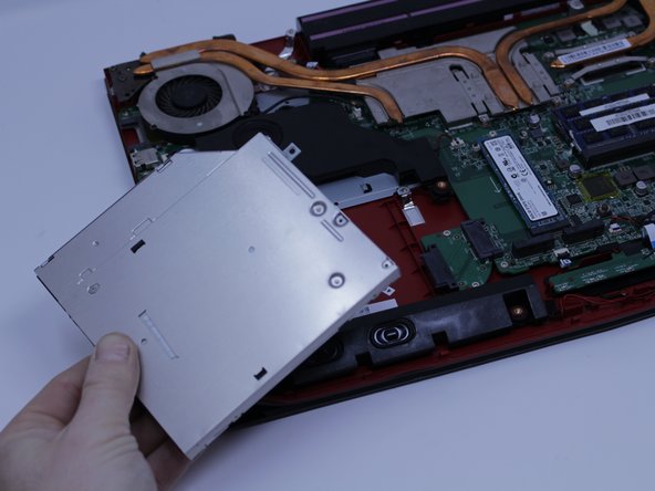
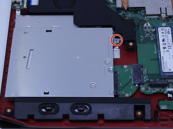
Carefully slide the Optical Drive off of the SATA connector.
-
The red marker shows the location for where the retaining screw comes through the back panel to hold the Optical Drive.
-
-
Questo passaggio è privo di traduzione. Aiuta a tradurlo
-
When you open the back cover, the RAM will be located as shown in the picture.
-
-
Questo passaggio è privo di traduzione. Aiuta a tradurlo
-
Press the hinges on the sides of the RAM chip as shown in the picture, in order to unlock it.
-
Carefully, slide it out at a 45 degree angle.
-
-
Questo passaggio è privo di traduzione. Aiuta a tradurlo
-
Similarly, press on the hinges on the sides of the other RAM chip, in order to unlock it.
-
-
Questo passaggio è privo di traduzione. Aiuta a tradurlo
-
Remove the single 5.5mm Phillips #1 screw attaching the SSD to the laptop.
-
-
Questo passaggio è privo di traduzione. Aiuta a tradurlo
-
Pull out the SSD by gently wiggling it from side to side until it comes out.
-
-
Questo passaggio è privo di traduzione. Aiuta a tradurlo
-
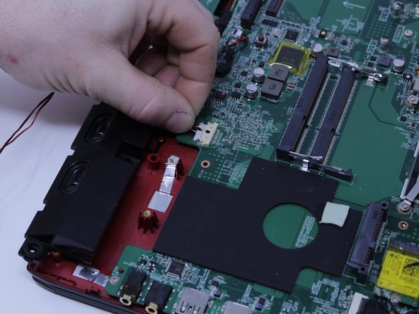
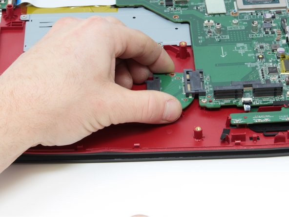
Pull upward to lift the front speakers and sub-woofer out of place.
-
Carefully slide out the connectors for both of the speaker systems.
-
-
Questo passaggio è privo di traduzione. Aiuta a tradurlo
-
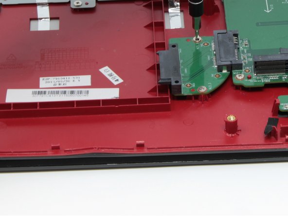
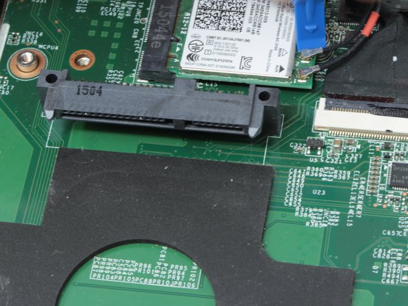
Use the Phillips #0 Screwdriver to remove the two 4mm screws that are holding the SATA connector in place.
-
-
Questo passaggio è privo di traduzione. Aiuta a tradurlo
-
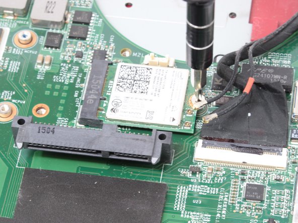
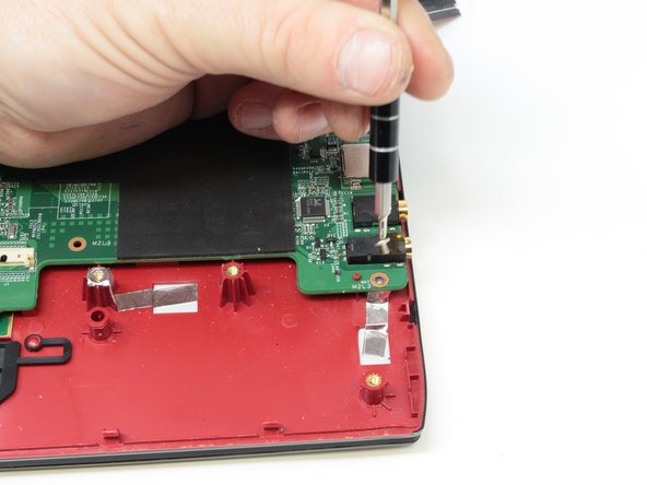
Remove the WIFI card by disconnecting the two coax cables and removing the retaining screw.
-
-
Questo passaggio è privo di traduzione. Aiuta a tradurlo
-
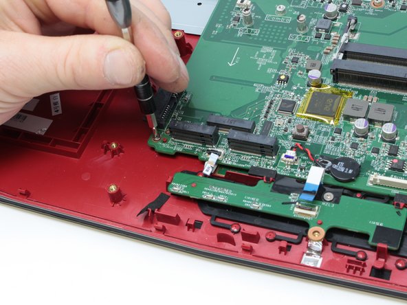
Use the plastic opening tool to pry up the connector that holds the display cable so it can be disconnected.
-
-
Questo passaggio è privo di traduzione. Aiuta a tradurlo
-
Remove the SD card reader by unscrewing the two 3 mm screws that hold it in place.
-
-
Questo passaggio è privo di traduzione. Aiuta a tradurlo
-
Remove the power and USB connectors that are connected to the left side of the motherboard by pulling them from the motherboard and SD card reader respectively.
-
-
Questo passaggio è privo di traduzione. Aiuta a tradurlo
-
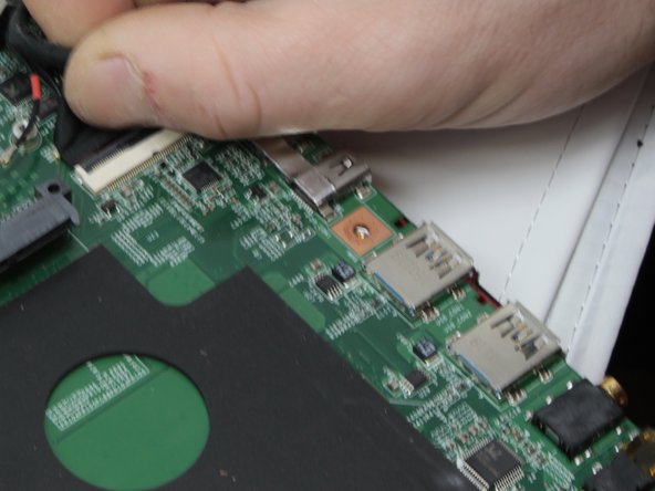
Disconnect the motherboard from the mouse key control board by pulling the connector out.
-
-
Questo passaggio è privo di traduzione. Aiuta a tradurlo
-
Disconnect the keyboard from the motherboard by carefully sliding the connectors out of the connections on the motherboard
-
-
Questo passaggio è privo di traduzione. Aiuta a tradurlo
-
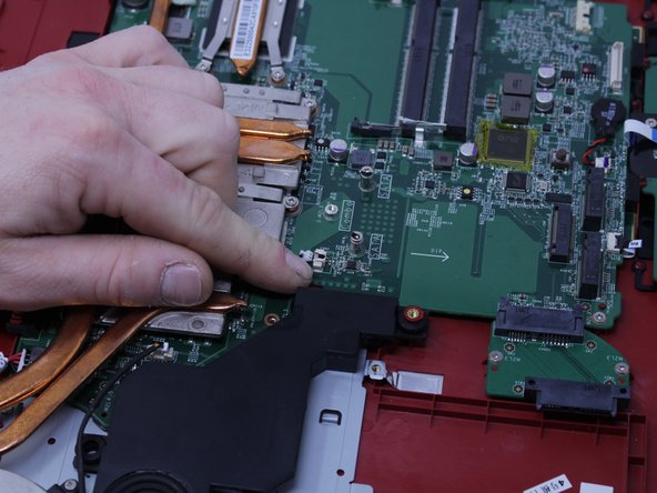
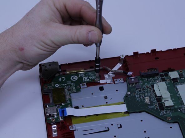
Use the Phillips #0 screwdriver to remove the three 3.8 mm standoff screws that retain the motherboard and carefully remove it.
-
-
Questo passaggio è privo di traduzione. Aiuta a tradurlo
-
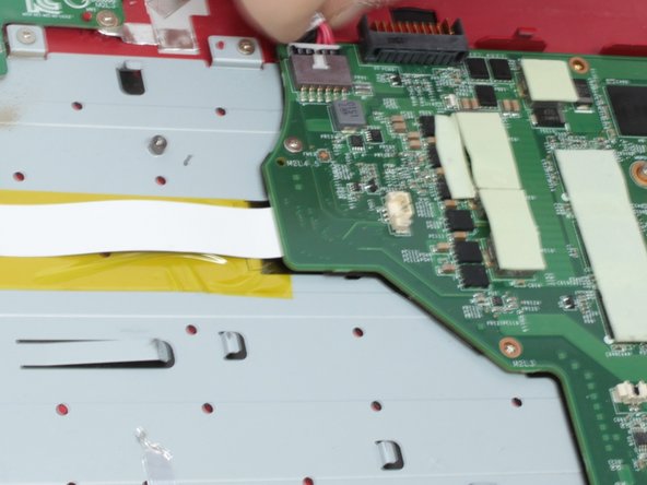
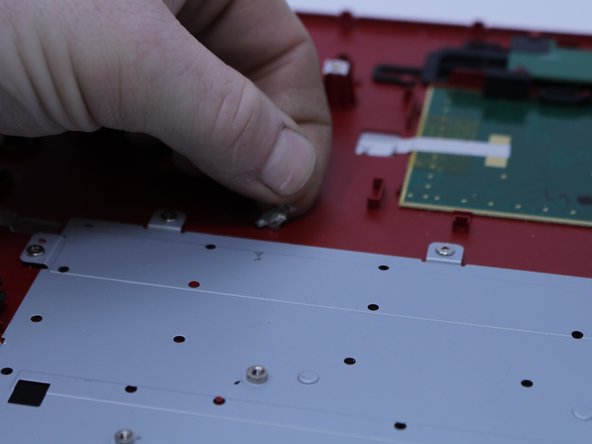
Peel the silver tape off of the keyboard back plate.
-
-
Questo passaggio è privo di traduzione. Aiuta a tradurlo
-
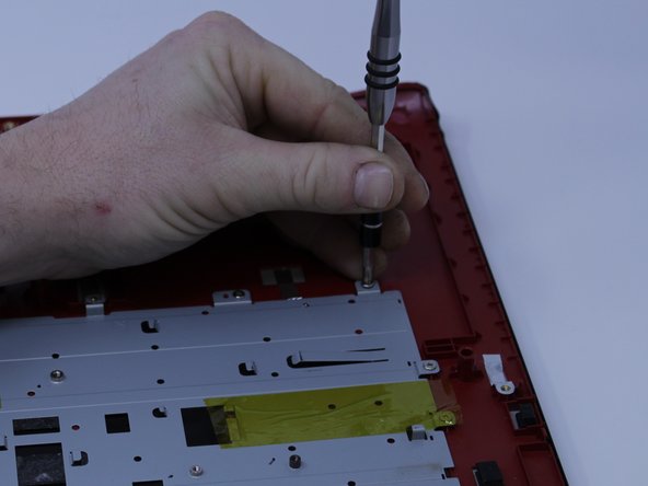
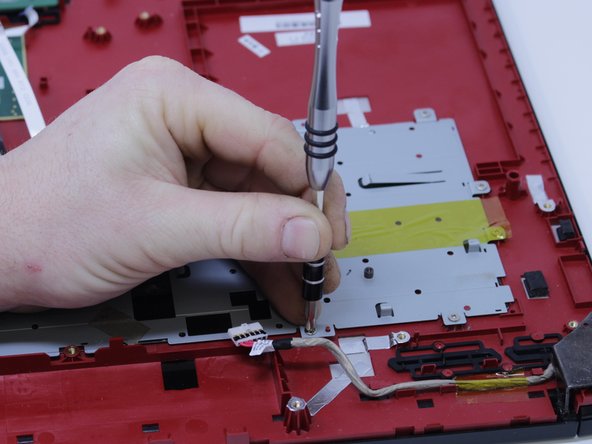
Remove the thirteen 3 mm screws that fasten the keyboard in place.
-
-
Questo passaggio è privo di traduzione. Aiuta a tradurlo
-
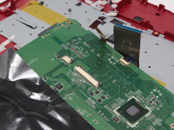
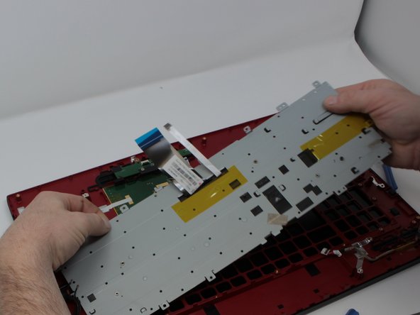
Peel the yellow tape off of the back plate to free the keyboard so it can be separated from the plate.
-


Annulla: non ho completato questa guida.
Altre 9 persone hanno completato questa guida.
Team

Central Washington University, Team S1-G2, Pengilly Fall 2017 Membro di Central Washington University, Team S1-G2, Pengilly Fall 2017
CWU-PENGILLY-F17S1G2
4 Membri
4 Guide realizzate
3 Commenti
1) Remove a single CD/DVD tray screw when the bottom cover is still on.
2) Remove the CD/DVD tray.
3) Remove the rear trim.
4) Remove the bottom cover from the CD/DVD side to the USB side, as the bottom cover has a frame that goes around the USB ports.
Otherwise, TY for your effort.
Someone please correct the time on this guide. There’s no way this is a 10 minute job!!
Plus the replacement keyboard (not bought yet) doesn’t seem to have the screw mount holes around the frame? Are there some steps missing to transplate the backing plate from the old keyboard to the new? Or should the new come with a backing plate with the required screw holes?