Questa versione può contenere modifiche errate. Passa all'ultima istantanea verificata.
Cosa ti serve
-
Questo passaggio è privo di traduzione. Aiuta a tradurlo
-
Using a plastic opening tool, lift up the rubber pad.
-
From the bottom of the device, with your fingers, pull back the rubber pad. This will expose the screw holes.
-
On the bottom of the hub, repeat the step above for the second rubber pad.
-
-
Questo passaggio è privo di traduzione. Aiuta a tradurlo
-
With the PH00 bit, remove the four 6mm Phillips screws.
-
-
-
Questo passaggio è privo di traduzione. Aiuta a tradurlo
-
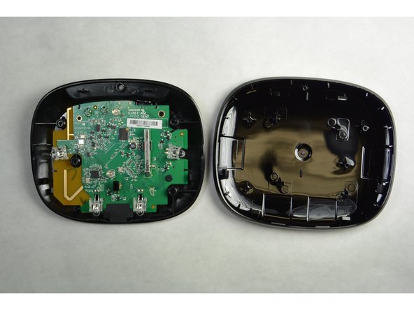
With the plastic opening tool, separate the pieces of plastic from each other
-
-
Questo passaggio è privo di traduzione. Aiuta a tradurlo
-
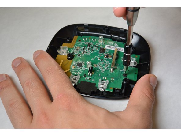
With the PH00 bit, remove the three 4mm Phillips screws.
-
-
Questo passaggio è privo di traduzione. Aiuta a tradurlo
-
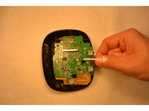
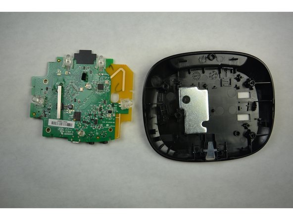
From the yellow corner, pry the circuit board from the housing..
-
-
Questo passaggio è privo di traduzione. Aiuta a tradurlo
-
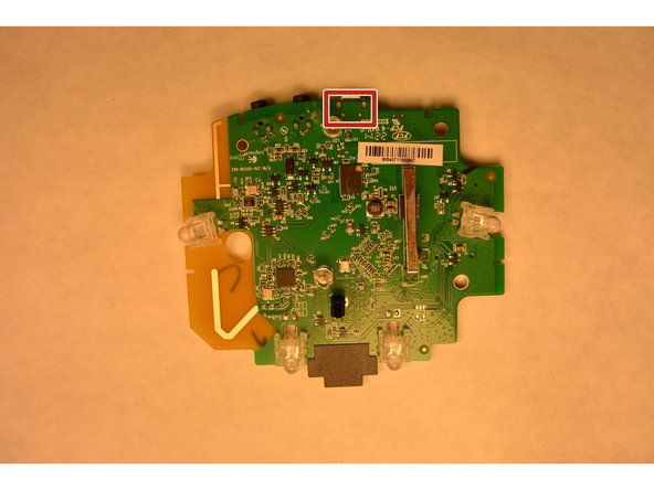
Locate the defective reset button.
-
Turn the board around to expose the reset solder.
-
Using soldering iron, remove solder and reset button. Replace reset button and solder.
-


Team

IUPUI, Team 3-2, Harley Fall 2015 Membro di IUPUI, Team 3-2, Harley Fall 2015
IUPUI-HARLEY-F15S3G2
4 Membri
5 Guide realizzate