Questa versione può contenere modifiche errate. Passa all'ultima istantanea verificata.
Cosa ti serve
-
Questo passaggio è privo di traduzione. Aiuta a tradurlo
-
Insert a large plastic opening tool next to the Kindle's headphone jack.
-
Move the plastic opening tool evenly around the Kindle, separating the two halves.
-
-
Questo passaggio è privo di traduzione. Aiuta a tradurlo
-
Set the Kindle down on the rear case.
-
Holding the display assembly near the camera, carefully open the display assembly up to about 90 degrees from the rear case.
-
-
-
Questo passaggio è privo di traduzione. Aiuta a tradurlo
-
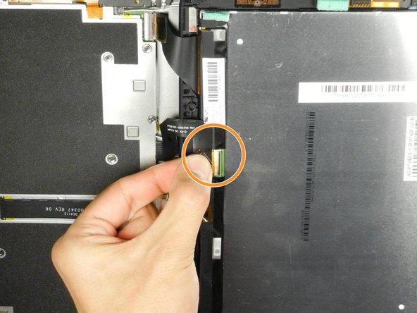
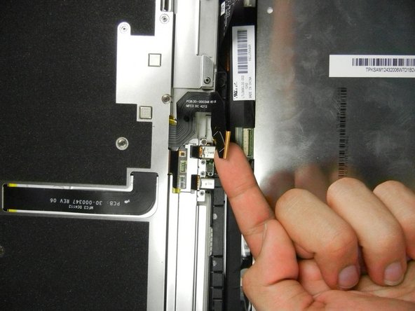
Lift the retaining flap on the ZIF connector of the upper flex cable.
-
Gently pull the cable out of its socket.
-
-
Questo passaggio è privo di traduzione. Aiuta a tradurlo
-
Separate the display assembly from the rest of the device.
-
-
Questo passaggio è privo di traduzione. Aiuta a tradurlo
-
Remove the following sixteen screws from the metal midframe on the rear of the device:
-
Four 3 mm Phillips screw (located in each corner of the device - noted in red in the diagram)
-
Four 3 mm Phillips screws (surrounding the ports - noted in orange in the diagram)
-
Eight 3 mm Phillips screws (located around the body of the midframe - noted in yellow in the diagram)
-


Annulla: non ho completato questa guida.
Un'altra persona ha completato questa guida.
Team

Cal Poly, Team 5-16, Forte Winter 2013 Membro di Cal Poly, Team 5-16, Forte Winter 2013
CPSU-FORTE-W13S5G16
5 Membri
14 Guide realizzate
2 Commenti
I suggest not removing the cables (steps 3,4 and 5) because it seems impossible to reconnect them.
Those are ZIF connectors—flip up the locking tab to release the cable, and you can remove/reinsert it freely.