Questa versione può contenere modifiche errate. Passa all'ultima istantanea verificata.
Cosa ti serve
-
Questo passaggio è privo di traduzione. Aiuta a tradurlo
-
Place the device face down on a clean cloth or another smooth surface.
-
Insert the plastic opening tool between the device’s front and back panels. You might need to wiggle the tool up and down to wedge it in the gap.
-
Maneuver the tool around the device until the back unclips from the front panel.
-
-
Questo passaggio è privo di traduzione. Aiuta a tradurlo
-
Carefully separate the back panel from the rest of the device internals.
-
-
Questo passaggio è privo di traduzione. Aiuta a tradurlo
-
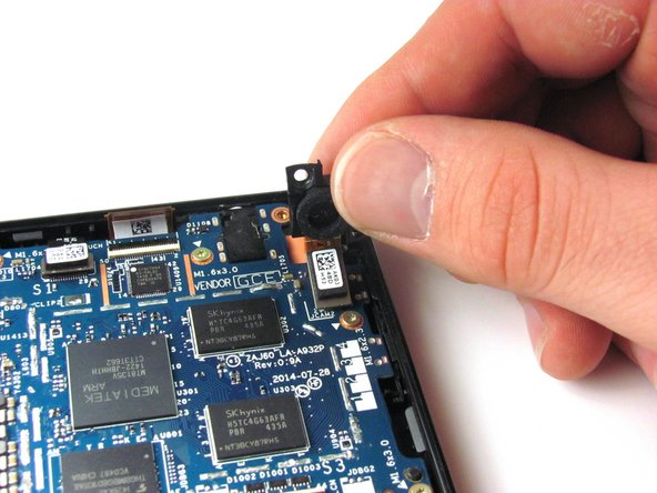
Unscrew the two 3.5mm T5 Torx Screws from the top of the camera.
-
-
Questo passaggio è privo di traduzione. Aiuta a tradurlo
-
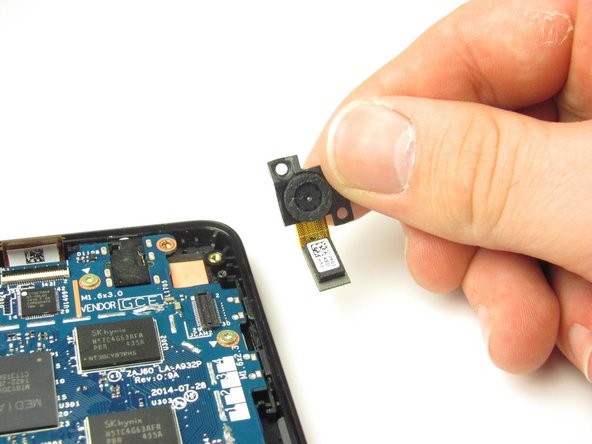
Gently pull the camera up and out of the device. As you pull, unclip the black and white connector with orange tape by popping it off at its base.
-
-
Questo passaggio è privo di traduzione. Aiuta a tradurlo
-
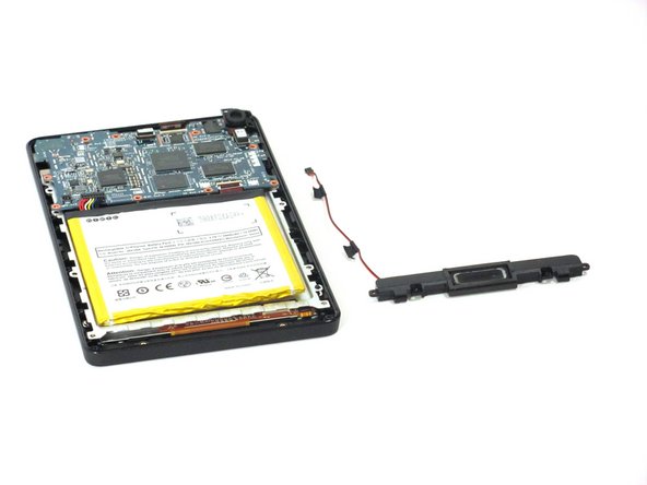
Unscrew the two 3.5mm T5 Torx screws at the base of the speaker.
-
-
-
Questo passaggio è privo di traduzione. Aiuta a tradurlo
-
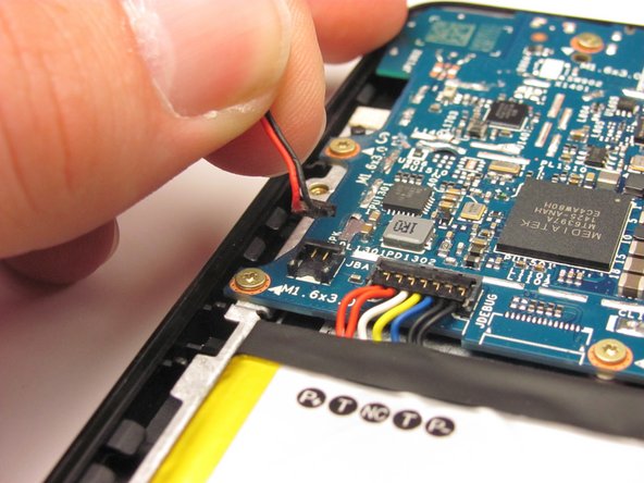
Unclip the speaker wire that runs up the side of the battery and clips into the motherboard next to the battery connector. Gently pull it straight up.
-
-
Questo passaggio è privo di traduzione. Aiuta a tradurlo
-
Gently pry the battery free from the adhesive holding it in place.
-
If you're having trouble working the battery free, warm it up with an iOpener or hair dryer to soften the adhesive, and then slide a credit card behind the battery to break up the adhesive.
-
-
Questo passaggio è privo di traduzione. Aiuta a tradurlo
-
Remove the multi-colored connector that joins the battery and the motherboard by pulling it straight up.
-
Remove the battery.
-
-
Questo passaggio è privo di traduzione. Aiuta a tradurlo
-
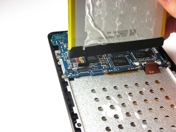
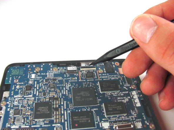
Use the tip of the spudger to disconnect the two zero insertion force connectors on the bottom and top of the motherboard.
-
The first connector is attached to an orange tape, and is located in the bottom-right corner of the motherboard. Remove this connector.
-
The second connector is long and thin, and is located at the top of the motherboard, a bit to the right of center. Remove this connector.
-
-
Questo passaggio è privo di traduzione. Aiuta a tradurlo
-
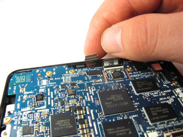
Disconnect the black and white connector at the very top-center of the motherboard by unclipping it using the flat side of the spudger.
-
-
Questo passaggio è privo di traduzione. Aiuta a tradurlo
-
Unscrew the ten 3.5mm T5 Torx screws around the edge of the motherboard.
-
-
Questo passaggio è privo di traduzione. Aiuta a tradurlo
-
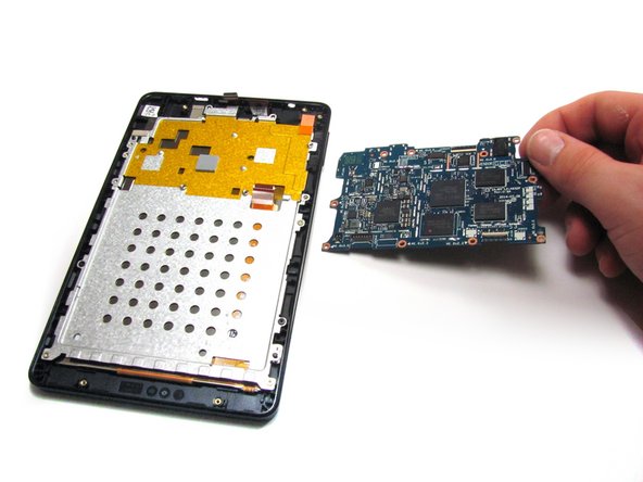
Starting from the bottom, lift the motherboard out of the device. You will have to push the motherboard about two millimeters toward the top of the device to unhook the top edge.
-


Annulla: non ho completato questa guida.
Altre 3 persone hanno completato questa guida.
Team

Cal Poly, Team 70-4, Forte Winter 2015 Membro di Cal Poly, Team 70-4, Forte Winter 2015
CPSU-FORTE-W15S70G4
4 Membri
12 Guide realizzate