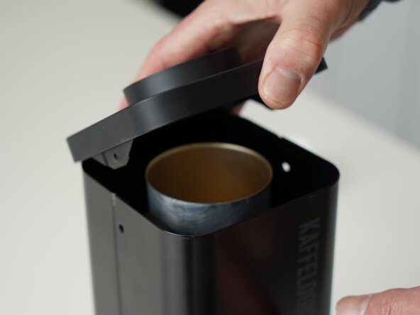
Salta al contenuto principale

Kaffelogic Nano 7/LINK (A/B/C-N Serial) LCD Board Replacement

Cosa ti serve

  1. Kaffelogic Nano 7/LINK (A/B/C-N Serial) LCD Board Replacement, Removing Panel Screws: passo 1, immagine 1 di 2 Kaffelogic Nano 7/LINK (A/B/C-N Serial) LCD Board Replacement, Removing Panel Screws: passo 1, immagine 2 di 2
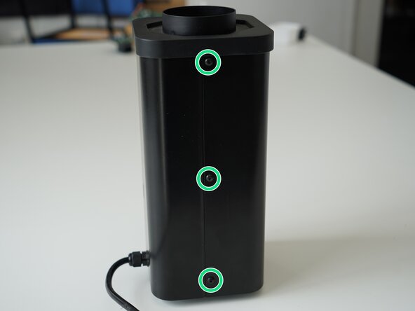
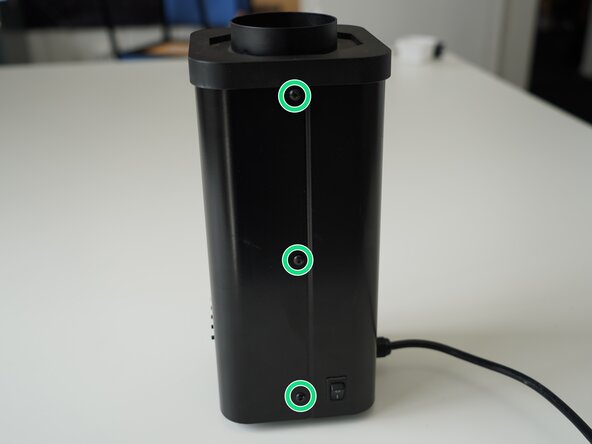
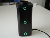
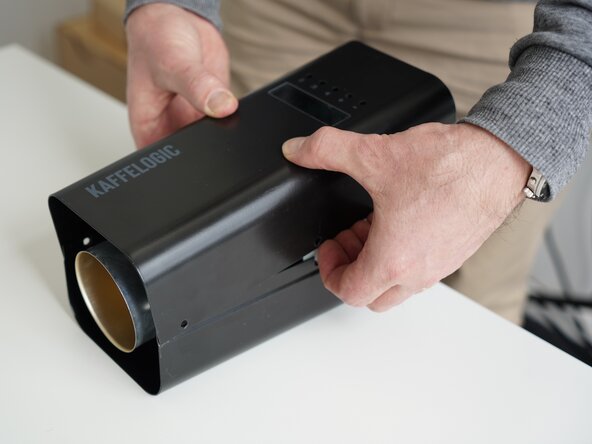
    • Remove the 6x 2.5mm Hex screws on the left and right side of the roaster.

  2. Kaffelogic Nano 7/LINK (A/B/C-N Serial) LCD Board Replacement, Lift the closure: passo 2, immagine 1 di 2 Kaffelogic Nano 7/LINK (A/B/C-N Serial) LCD Board Replacement, Lift the closure: passo 2, immagine 2 di 2
    • Hold the roaster steady while removing the plastic top/closure.

    • Panels may spring apart slightly once removed.

  3. Kaffelogic Nano 7/LINK (A/B/C-N Serial) LCD Board Replacement, Remove bottom panel screws: passo 3, immagine 1 di 3 Kaffelogic Nano 7/LINK (A/B/C-N Serial) LCD Board Replacement, Remove bottom panel screws: passo 3, immagine 2 di 3 Kaffelogic Nano 7/LINK (A/B/C-N Serial) LCD Board Replacement, Remove bottom panel screws: passo 3, immagine 3 di 3
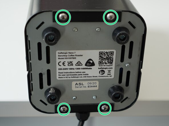
    • Remove the 4x 2.5mm Hex screws on the bottom of the roaster.

  4. Kaffelogic Nano 7/LINK (A/B/C-N Serial) LCD Board Replacement, Remove the front panel: passo 4, immagine 1 di 3 Kaffelogic Nano 7/LINK (A/B/C-N Serial) LCD Board Replacement, Remove the front panel: passo 4, immagine 2 di 3 Kaffelogic Nano 7/LINK (A/B/C-N Serial) LCD Board Replacement, Remove the front panel: passo 4, immagine 3 di 3
    • Pull away the front panel carefully.

    • Take care not to damage the buttons while maneuvering the front panel.

  5. Kaffelogic Nano 7/LINK (A/B/C-N Serial) LCD Board Replacement, Remove rear panel: passo 5, immagine 1 di 3 Kaffelogic Nano 7/LINK (A/B/C-N Serial) LCD Board Replacement, Remove rear panel: passo 5, immagine 2 di 3 Kaffelogic Nano 7/LINK (A/B/C-N Serial) LCD Board Replacement, Remove rear panel: passo 5, immagine 3 di 3
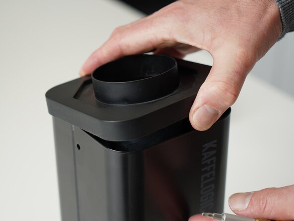
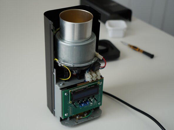
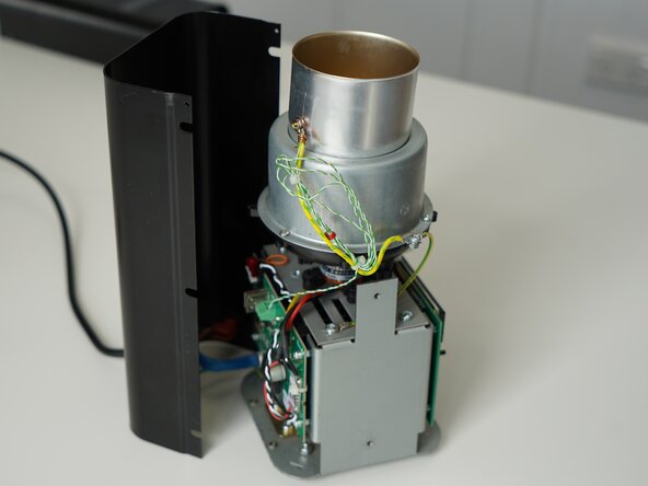
    • Stand the roaster up again and pull away the rear panel from the chassis to expose the remaining components.

    • The mains cable is routed through the panel and it will remain attached, place the panel in a soft bag if you wish to protect the paint throughout the rest of your repairs.

  6. Kaffelogic Nano 7/LINK (A/B/C-N Serial) LCD Board Replacement, Remove PCB screws: passo 6, immagine 1 di 3 Kaffelogic Nano 7/LINK (A/B/C-N Serial) LCD Board Replacement, Remove PCB screws: passo 6, immagine 2 di 3 Kaffelogic Nano 7/LINK (A/B/C-N Serial) LCD Board Replacement, Remove PCB screws: passo 6, immagine 3 di 3
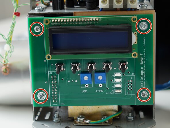
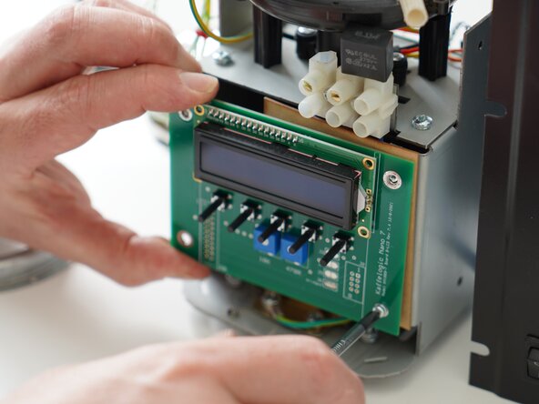
    • Remove the 4x PH2 screws securing the display board to the chassis.

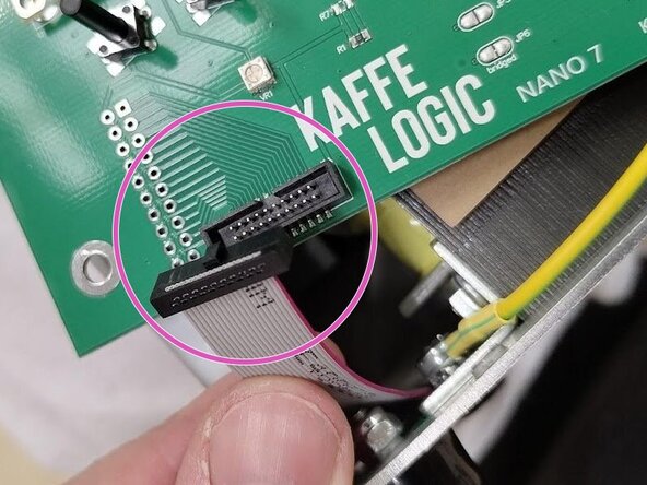
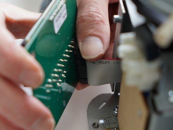
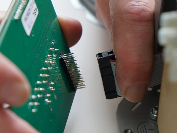
    • If your ribbon cable is mounted on the front, disconnect it before unscrewing the PCB.

  7. Kaffelogic Nano 7/LINK (A/B/C-N Serial) LCD Board Replacement, Remove ribbon connector: passo 7, immagine 1 di 2 Kaffelogic Nano 7/LINK (A/B/C-N Serial) LCD Board Replacement, Remove ribbon connector: passo 7, immagine 2 di 2
    • Pull carefully on the ribbon connector to remove it.

Conclusione

To reassemble your device, follow these instructions in reverse order.

Kaffelogic

Membro da: 07/23/25

2.098 Reputazione

18 Guide realizzate

0Commenti sulla guida

Aggiungi Commento

Visualizza Statistiche:

Ultime 24 Ore: 0

Ultimi 7 Giorni: 1

Ultimi 30 Giorni: 10

Tutti i Tempi: 36