Salta al contenuto principale

Handspring Visor Deluxe PDA Motherboard and Memory card I/O Replacement

Cosa ti serve

  1. Handspring Visor Deluxe PDA Motherboard and Memory card I/O Replacement, Outside cover and stylus: passo 1, immagine 1 di 2 Handspring Visor Deluxe PDA Motherboard and Memory card I/O Replacement, Outside cover and stylus: passo 1, immagine 2 di 2
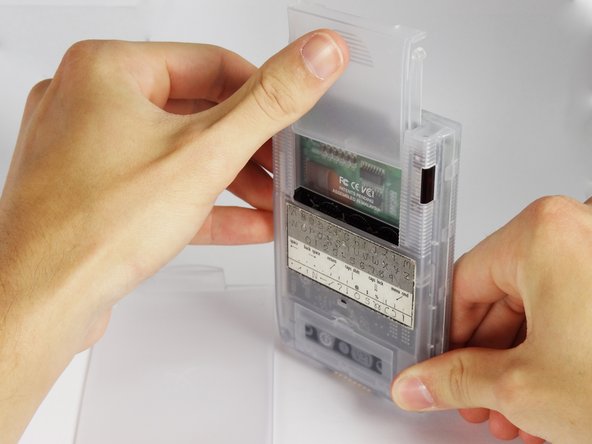
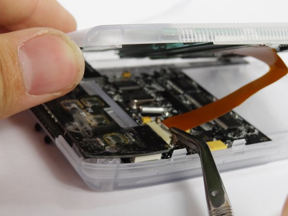
    • Remove the outer screen cover by releasing the top clip from the main body of the device.

  2. Handspring Visor Deluxe PDA Motherboard and Memory card I/O Replacement: passo 2, immagine 1 di 3 Handspring Visor Deluxe PDA Motherboard and Memory card I/O Replacement: passo 2, immagine 2 di 3 Handspring Visor Deluxe PDA Motherboard and Memory card I/O Replacement: passo 2, immagine 3 di 3
    • Pull out the stylus from the top right corner of the device.

  3. Handspring Visor Deluxe PDA Motherboard and Memory card I/O Replacement: passo 3, immagine 1 di 3 Handspring Visor Deluxe PDA Motherboard and Memory card I/O Replacement: passo 3, immagine 2 di 3 Handspring Visor Deluxe PDA Motherboard and Memory card I/O Replacement: passo 3, immagine 3 di 3
    • Slide the memory cartridge cover up and off the device.

  4. Handspring Visor Deluxe PDA Motherboard and Memory card I/O Replacement, Batteries: passo 4, immagine 1 di 2 Handspring Visor Deluxe PDA Motherboard and Memory card I/O Replacement, Batteries: passo 4, immagine 2 di 2
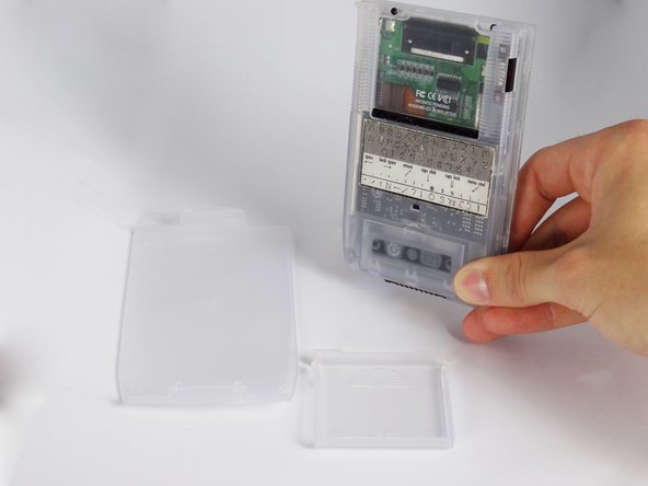
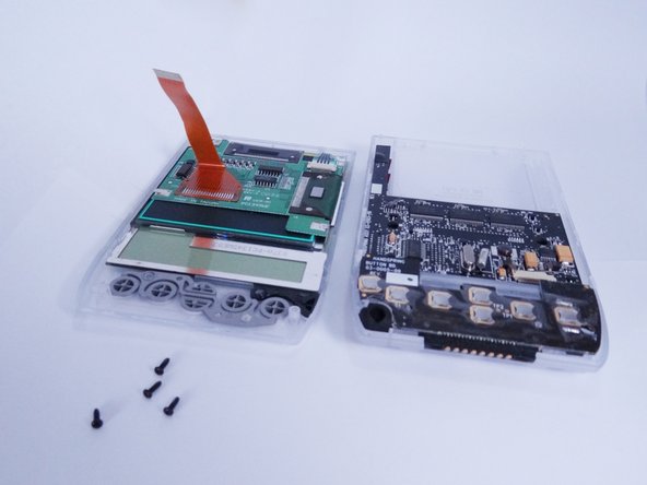
    • Remove the battery cover by releasing the clip from the main body of the device.

  5. Handspring Visor Deluxe PDA Motherboard and Memory card I/O Replacement: passo 5, immagine 1 di 1
    • Remove the batteries from the device.

  6. Handspring Visor Deluxe PDA Motherboard and Memory card I/O Replacement, Back Cover: passo 6, immagine 1 di 1
    • Unscrew the four 2.94mm screws with a #00 Phillips screwdriver.

    • One end of the OEM stylus can unscrew and contains a mini #00 Phillips screwdriver.

  7. Handspring Visor Deluxe PDA Motherboard and Memory card I/O Replacement: passo 7, immagine 1 di 3 Handspring Visor Deluxe PDA Motherboard and Memory card I/O Replacement: passo 7, immagine 2 di 3 Handspring Visor Deluxe PDA Motherboard and Memory card I/O Replacement: passo 7, immagine 3 di 3
    • Use the spudger to pry open the casing by applying pressure at 4 clips on both sides of the device.

    • Be careful while opening the casing as there is a flex strip connecting the two halves.

  8. Handspring Visor Deluxe PDA Motherboard and Memory card I/O Replacement: passo 8, immagine 1 di 3 Handspring Visor Deluxe PDA Motherboard and Memory card I/O Replacement: passo 8, immagine 2 di 3 Handspring Visor Deluxe PDA Motherboard and Memory card I/O Replacement: passo 8, immagine 3 di 3
    • Disconnect the flex strip from the motherboard with tweezers.

  9. Handspring Visor Deluxe PDA Motherboard and Memory card I/O Replacement, Button Pad and Battery Terminal: passo 9, immagine 1 di 1
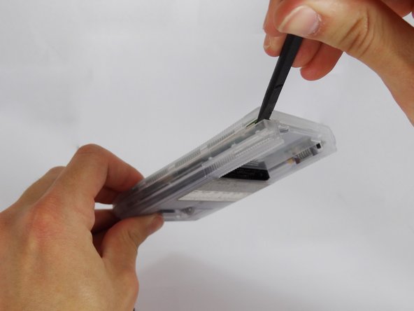
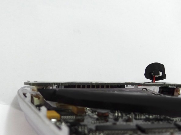
    • Use tweezers to remove the power button from the back case.

  10. Handspring Visor Deluxe PDA Motherboard and Memory card I/O Replacement: passo 10, immagine 1 di 3 Handspring Visor Deluxe PDA Motherboard and Memory card I/O Replacement: passo 10, immagine 2 di 3 Handspring Visor Deluxe PDA Motherboard and Memory card I/O Replacement: passo 10, immagine 3 di 3
    • Disconnect the button pad by using the spudger to pry it off the motherboard.

    • Remove the button pad.

  11. Handspring Visor Deluxe PDA Motherboard and Memory card I/O Replacement, Motherboard and Memory card I/O: passo 11, immagine 1 di 2 Handspring Visor Deluxe PDA Motherboard and Memory card I/O Replacement, Motherboard and Memory card I/O: passo 11, immagine 2 di 2
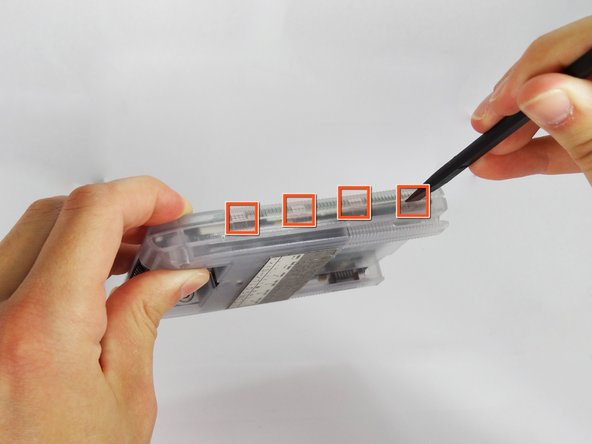
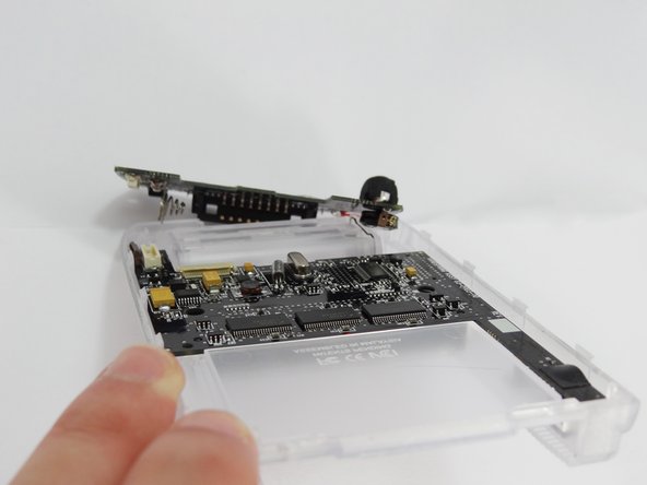
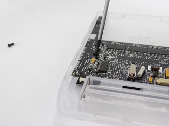
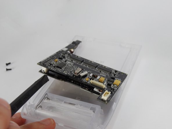
    • Unscrew the two 2.94mm Phillips #00 screws that hold the motherboard in place.

  12. Handspring Visor Deluxe PDA Motherboard and Memory card I/O Replacement: passo 12, immagine 1 di 3 Handspring Visor Deluxe PDA Motherboard and Memory card I/O Replacement: passo 12, immagine 2 di 3 Handspring Visor Deluxe PDA Motherboard and Memory card I/O Replacement: passo 12, immagine 3 di 3
    • Use the spudger to lift the motherboard from the case.

Conclusione

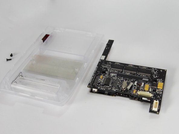
To reassemble your device, follow these instructions in reverse order.

Un'altra persona ha completato questa guida.

Team

Cal Poly, Team 1-2, Regan SU 2012 Membro di Cal Poly, Team 1-2, Regan SU 2012

CPSU-REGAN-SU12S1G2

4 Membri

6 Guide realizzate

0 Commenti

Aggiungi Commento

Visualizza Statistiche:

Ultime 24 Ore: 0

Ultimi 7 Giorni: 1

Ultimi 30 Giorni: 4

Tutti i Tempi: 1,051