Questa versione può contenere modifiche errate. Passa all'ultima istantanea verificata.
Cosa ti serve
-
Questo passaggio è privo di traduzione. Aiuta a tradurlo
-
Turn over the Vive controller so that the bottom saucer is facing up.
-
Use the T5 Torx screwdriver to remove three black 21mm screws from the bottom saucer.
-
-
Questo passaggio è privo di traduzione. Aiuta a tradurlo
-
Use the nylon spudger to separate the top and bottom saucer covers all around the edges.
-
Remove only the top saucer cover by pulling up with your hand.
-
-
Questo passaggio è privo di traduzione. Aiuta a tradurlo
-
Use the Phillips 00 screwdriver to remove the three silver 12.8mm screws from the exposed upper sensor panel.
-
-
Questo passaggio è privo di traduzione. Aiuta a tradurlo
-
Carefully pull away the bottom saucer cover with your hand.
-
-
Questo passaggio è privo di traduzione. Aiuta a tradurlo
-
Use the T5 Torx screwdriver to remove the two black 5.2mm screws on the back gray panel.
-
-
Questo passaggio è privo di traduzione. Aiuta a tradurlo
-
Turn over the Vive controller so that the exposed bottom saucer panel is facing up.
-
Use the T5 Torx screwdriver to remove the three black 5.2mm screws.
-
-
Questo passaggio è privo di traduzione. Aiuta a tradurlo
-
Use the nylon spudger to separate the front panel gently by running the spudger around the edges of the handle.
-
Gently lift the right side of the panel to the left.
-
-
Questo passaggio è privo di traduzione. Aiuta a tradurlo
-
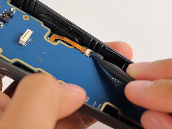
Disconnect the upper ribbon cable gently by pulling the ribbon up and away from the motherboard with two fingers.
-
-
-
Questo passaggio è privo di traduzione. Aiuta a tradurlo
-
Disconnect the middle ribbon cable gently by pulling the ribbon cable up and away from the motherboard with two fingers.
-
-
Questo passaggio è privo di traduzione. Aiuta a tradurlo
-
Use the nylon spudger to lift the white tab by 90 degrees.
-
Disconnect the bottom ribbon cable gently by pulling the ribbon cable down with two fingers.
-
-
Questo passaggio è privo di traduzione. Aiuta a tradurlo
-
Use the Phillips 00 screwdriver to remove two black 2.8mm screws from the silver plate.
-
Use the Phillips 00 screwdriver to remove the black 5.8mm screw from the bottom right corner of the silver plate.
-
-
Questo passaggio è privo di traduzione. Aiuta a tradurlo
-
Remove the silver plate by pinching it with two fingers and lifting up.
-
-
Questo passaggio è privo di traduzione. Aiuta a tradurlo
-
Use the Phillips 00 screwdriver to remove the black 5.8mm screw from the top left of the battery frame.
-
-
Questo passaggio è privo di traduzione. Aiuta a tradurlo
-
Use the T5 Torx screwdriver to remove the two silver 4.2mm screws from the bottom of the battery frame.
-
-
Questo passaggio è privo di traduzione. Aiuta a tradurlo
-
Disconnect the three-pin cable gently by pinching the cable with two fingers and pulling up.
-
-
Questo passaggio è privo di traduzione. Aiuta a tradurlo
-
Lift the battery frame to remove the battery from the Vive controller
-
-
Questo passaggio è privo di traduzione. Aiuta a tradurlo
-
Use the Phillips 00 screwdriver to remove the two black 5.8mm screws from the top of the motherboard.
-
-
Questo passaggio è privo di traduzione. Aiuta a tradurlo
-
Use the T5 Torx screwdriver to remove the two silver 4.2mm screws from the bottom of the motherboard.
-
-
Questo passaggio è privo di traduzione. Aiuta a tradurlo
-
Use the nylon spudger to rotate the black tab up by 90 degrees.
-
Disconnect the ribbon cable carefully with your finger.
-
-
Questo passaggio è privo di traduzione. Aiuta a tradurlo
-
Lift the motherboard up and out of the Vive controller using your hands.
-
-
Questo passaggio è privo di traduzione. Aiuta a tradurlo
-
Use the Phillips 00 screwdriver to remove the two black 5.8mm screws from the silver rectangular plate.
-
-
Questo passaggio è privo di traduzione. Aiuta a tradurlo
-
Lift the silver rectangular plate up and out of the controller using your hand.
-
-
Questo passaggio è privo di traduzione. Aiuta a tradurlo
-
Use the nylon spudger to lift the bottom rubber tab on the inside of the right grip button.
-
Use the nylon spudger to lift the top rubber tab on the inside of the right grip button.
-
-
Questo passaggio è privo di traduzione. Aiuta a tradurlo
-
Push the grip button in with your finger until it pops out of its socket.
-
Repeat steps 23 and 24 to remove the left side grip button.
-


Annulla: non ho completato questa guida.
Un'altra persona ha completato questa guida.
Team

Cal Poly, Team S15-G5, Livingston Fall 2017 Membro di Cal Poly, Team S15-G5, Livingston Fall 2017
CPSU-LIVINGSTON-F17S15G5
4 Membri
51 Guide realizzate
2 Commenti
It’s all fine and dandy but this part is nowhere to be found
Hi, first of all ty for the tools and all the effort.
During disassembly my system button's 7 contanct fpc connector ripped apart and cant find any label on it.
I am trying to find a replacement part to re-solder it.
Can you help me with a name of that connector.
Thanks