Questa versione può contenere modifiche errate. Passa all'ultima istantanea verificata.
Cosa ti serve
-
-
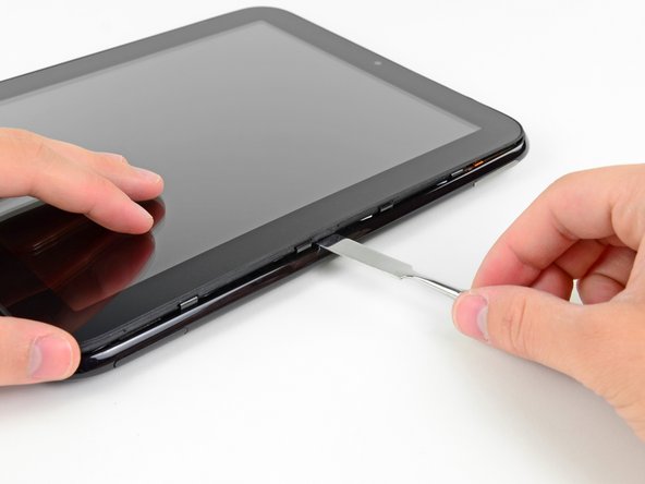
Nei passaggi seguenti, utilizzerai uno spudger di metallo per togliere il pannello frontale dal case posteriore del tuo TouchPad.
-
-
-
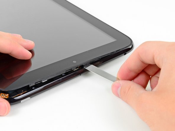
Inserisci uno spudger piatto di metallo nello spazio tra l'anello esterno in gomma sul gruppo pannello frontale e il case posteriore in plastica nera vicino al connettore USB.
-
Solleva il gruppo pannello frontale dal case posteriore, facendo attenzione a non danneggiare l'LCD o il pannello di vetro.
-
-
-
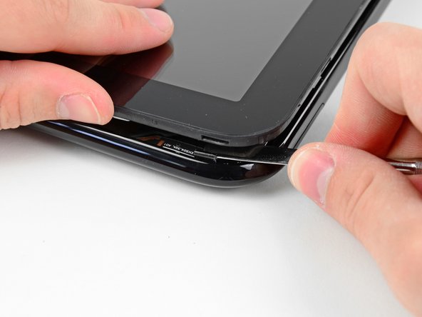
Come nel passaggio precedente, usa uno spudger per sollevare il pannello frontale dal case posteriore lungo il suo lato lungo, dalla parte del TouchPad con il pulsante del volume.
-
Continua a sollevare il gruppo pannello frontale lungo il lato del pulsante del volume del TouchPad finché non si forma uno spazio tra esso e il case posteriore.
-
-
-
Questo passaggio è privo di traduzione. Aiuta a tradurlo
-
Use the edge of a plastic opening tool to peel up the two pieces of copper tape covering the USB connector board near the battery and the motherboard.
-
-
Questo passaggio è privo di traduzione. Aiuta a tradurlo
-
Remove the four 3.2 mm Phillips screws securing the USB connector board to the rear case.
-
-
Questo passaggio è privo di traduzione. Aiuta a tradurlo
-
Pry the upper end of the USB connector board upwards to disconnect it from its socket on the logic board.
-
-
Questo passaggio è privo di traduzione. Aiuta a tradurlo
-
Pull the USB connector board away from the bottom edge of the rear case and lift, but do not remove it out of its housing.
-
-
Questo passaggio è privo di traduzione. Aiuta a tradurlo
-
Pull the vibrator motor connector straight away from its socket on the USB connector board.
-
Remove the USB connector board from the TouchPad.
-
NOTE: First verify that there is a connector before pulling! The vibrator motor may be soldered directly to the USB Board requiring the motor to be pried up and removed together with the board.
-
-
Questo passaggio è privo di traduzione. Aiuta a tradurlo
-
Use the edge of a plastic opening tool to flip up the retaining flap on the volume control/power button ribbon cable socket.
-
Pull the cable out of its socket.
-
-
Questo passaggio è privo di traduzione. Aiuta a tradurlo
-
Use a plastic opening tool to lift the camera connector up and out of its socket on the motherboard.
-
Bend the camera cable away from the motherboard.
-
-
Questo passaggio è privo di traduzione. Aiuta a tradurlo
-
Carefully flip up the retaining flap on the microphone cable socket.
-
Pull the microphone cable out of its socket.
-
-
Questo passaggio è privo di traduzione. Aiuta a tradurlo
-
Use your plastic opening tool to pry the upper antenna connector up from its socket on the motherboard.
-
-
Questo passaggio è privo di traduzione. Aiuta a tradurlo
-
Pry up the retaining flap on the headphone jack ribbon cable socket.
-
Pull the headphone jack ribbon cable out of its socket.
-
-
Questo passaggio è privo di traduzione. Aiuta a tradurlo
-
Pry the speaker cable connector up from its socket on the motherboard.
-
-
Questo passaggio è privo di traduzione. Aiuta a tradurlo
-
Use a plastic opening tool to flip up the retaining flap on the digitizer board ribbon cable socket.
-
Pull the digitizer ribbon cable out of its socket.
-
-
Questo passaggio è privo di traduzione. Aiuta a tradurlo
-
Pry up the lower antenna cable connector from its socket on the motherboard.
-
-
Questo passaggio è privo di traduzione. Aiuta a tradurlo
-
De-route the lower antenna cable along the top edge of the battery and carefully pull it out from under its retaining clip near the top right corner of the battery.
-
-
Questo passaggio è privo di traduzione. Aiuta a tradurlo
-
Remove the eight 3.2 mm Phillips screws securing both the battery and the motherboard to the rear case.
-
-
Questo passaggio è privo di traduzione. Aiuta a tradurlo
-
Use a plastic opening tool to pry the battery up from the tape securing it to the rear case.
-
-
Questo passaggio è privo di traduzione. Aiuta a tradurlo
-
Lift the motherboard assembly out of the rear case, minding any cables that may get caught.
-
-
Questo passaggio è privo di traduzione. Aiuta a tradurlo
-
Carefully pull the battery away from the L-shaped motherboard to disconnect its cable.
-
Remove the battery from the motherboard.
-


Annulla: non ho completato questa guida.
Altre 57 persone hanno completato questa guida.

6 Commenti
Removing the screen is easily the most difficult, time consuming and frustrating part of the whole process. Once removed, the rest, while tedious, is not particularly difficult.
Very well done! I could have used a little more “here is a clip that holds the screen frame to the body frame…” because I was gently prying the screen out of its own frame. But luckily never snapped it.
i have 2 units, 1 of which went below battery critical and is in that protective state now where it won’t take a charge. Going to take the battery from the other unit so I can power this one on and the flash the battery system firmware to reset and hopefully initiate the charging capabilities.
i honestly can’t believe this was built back in 2011 because they did a pretty good job.
And I just happened to see an original charging barrel at my friends house while visiting in another state. He was just charging his iPhone with it so I begged him to trade me for a wall wart that I had. Super lucky find.
thanks again for posting this guide.
And to anyone still reading, the newest nightly builds will crash your touchpad for sure.
Written 4/3/2019
james
The newest nightly builds? I thought HP had totally abandoned the TouchPad.