Salta al contenuto principale
HP ProBook 4540s WLAN Module Replacement

HP ProBook 4540s WLAN Module Replacement

Amber Schindler

Amber Schindler e 2 altri collaboratori

Ultimo aggiornamento il December 22, 2016

5 minuti
Facile

Introduzione

Vai al passo 1

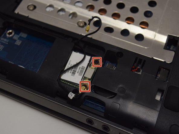
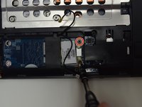
The WLAN module is used to power the Wi-Fi on the ProBook; not to be confused with the WWAN module that powers mobile broadband. The two modules are beside each other but the smaller module is WLAN which will be the focus for this guide.

Cosa ti serve

Strumenti

  1. HP ProBook 4540s WLAN Module Replacement, Battery: passo 1, immagine 1 di 1
    • Make sure the computer is shut off and the power cord is unplugged from the AC outlet.

    • Slide the two release latches on either side of the battery.

    • Gently tilt the battery upward and remove it from its socket.

  2. HP ProBook 4540s WLAN Module Replacement, Bottom Door: passo 2, immagine 1 di 1
    • Turn the computer so the bottom is facing towards you.

    • Remove the one 3.0 mm Phillips PM2.0x3.0 security screw.

    • The security screw is an optional feature and isn't required to hold the backing if there is not one screwed in place.

    • Slide the release latches then pull the door towards you. Lift the door away to completely remove it.

  3. HP ProBook 4540s WLAN Module Replacement, WLAN Module: passo 3, immagine 1 di 2 HP ProBook 4540s WLAN Module Replacement, WLAN Module: passo 3, immagine 2 di 2
    • Disconnect the antenna cables from their terminals in the WLAN module.

    • One cable is attached to the Auxiliary ("Aux") terminal, represented with a blue wire. The other cable is connected to the Main terminal which is usually represented with a red wire. These wires can be seen in little windows beside the component.

  4. HP ProBook 4540s WLAN Module Replacement: passo 4, immagine 1 di 2 HP ProBook 4540s WLAN Module Replacement: passo 4, immagine 2 di 2
    • Unscrew two 3.0 mm Phillips PM2.0x3.0 screw securing the module to the computer.

    • The edge of the module that is opposite of the slot is risen away from the computer.

    • Gently lift and remove the module.

Conclusione

To reassemble your device, follow these instructions in reverse order.

Altre 2 persone hanno completato questa guida.

Amber Schindler

Membro da: 10/26/16

1.042 Reputazione

6 Guide realizzate

Team

UW Tacoma, Team 1-5, Rose Fall 2016 Membro di UW Tacoma, Team 1-5, Rose Fall 2016

UWT-ROSE-F16S1G5

4 Membri

6 Guide realizzate

0Commenti sulla guida

Aggiungi Commento

Visualizza Statistiche:

Ultime 24 Ore: 0

Ultimi 7 Giorni: 3

Ultimi 30 Giorni: 24

Tutti i Tempi: 2,003