Questa versione può contenere modifiche errate. Passa all'ultima istantanea verificata.
Cosa ti serve
-
Questo passaggio è privo di traduzione. Aiuta a tradurlo
-
Rotate the printer 90 degrees counter clockwise so that the side panel next to control panel is facing you.
-
Remove the two T10 12mm Torx screws from the left side panel.
-
-
Questo passaggio è privo di traduzione. Aiuta a tradurlo
-
Firmly pull the the back of the side panel until it separates from the body of the printer.
-
Rotate the side panel upwards while pulling it towards yourself to remove the panel.
-
-
Questo passaggio è privo di traduzione. Aiuta a tradurlo
-
Rotate the printer 90 degrees clockwise.
-
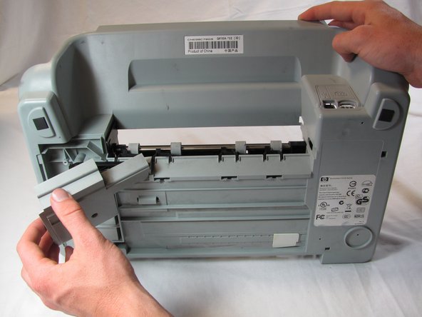
Grasp the paper tray and rotate it down.
-
Insert your fingers into the slot in the printer door and pull to rotate the gate down.
-
-
Questo passaggio è privo di traduzione. Aiuta a tradurlo
-
Rotate the printer 90 degrees clockwise.
-
Remove the two T10 12 mm Torx screws.
-
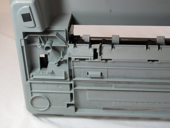
Grasp both sides of the side panel and pull it forward to remove the panel.
-
-
Questo passaggio è privo di traduzione. Aiuta a tradurlo
-
Rotate the printer 90 degrees counter clockwise.
-
Lift the scanner lid to expose the scanner glass.
-
-
Questo passaggio è privo di traduzione. Aiuta a tradurlo
-
Rotate the printer 90 degrees counter clockwise.
-
Inside the printer is a small white tab. Press it inward with a spudger until a pop is heard.
-
Remove the front panel by grasping its front and pulling away from the printer.
-
-
Questo passaggio è privo di traduzione. Aiuta a tradurlo
-
Rotate the printer 90 degrees clockwise.
-
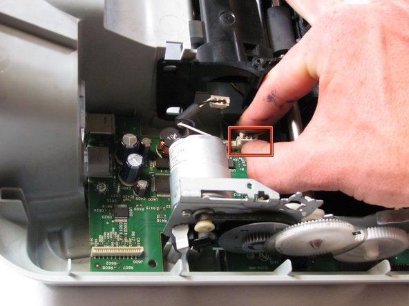
Remove the cable connecting the top panel of the printer to the power button assembly.
-
-
Questo passaggio è privo di traduzione. Aiuta a tradurlo
-
Carefully lift the top panel of the printer away from the printer body.
-
-
Questo passaggio è privo di traduzione. Aiuta a tradurlo
-
Set aside the top panel of the printer.
-
Remove the two T10 12 mm Torx screws from the top front of the printer
-
-
Questo passaggio è privo di traduzione. Aiuta a tradurlo
-
Rotate the Printer 90 degrees counter clockwise.
-
Remove the scanner cable from the main circuit board.
-
-
Questo passaggio è privo di traduzione. Aiuta a tradurlo
-
Rotate the printer 90 degrees clockwise.
-
Using both hands, lift the scanner tray from the body of the printer.
-
-
Questo passaggio è privo di traduzione. Aiuta a tradurlo
-
Remove the power button circuit board from the support frame by pinching the left side, and pulling forward and to the left simultaneously.
-
Push up on the tab holding the secondary control circuit board with the spudger and pull it forward to remove it.
-
-
-
Questo passaggio è privo di traduzione. Aiuta a tradurlo
-
Remove the two T10 12 mm Torx screws.
-
Lift the support frame off of the printer body with both hands.
-
-
Questo passaggio è privo di traduzione. Aiuta a tradurlo
-
Remove the printer door and paper tray by putting them in the closed position and not laying flat then rotating them upwards lift the left side up.
-
-
Questo passaggio è privo di traduzione. Aiuta a tradurlo
-
Remove both of the ink cartridges by grabbing the front of the ink cartridge and pulling down.
-
-
Questo passaggio è privo di traduzione. Aiuta a tradurlo
-
Remove the T10 6 mm Torx screw on the left side of the track assembly.
-
Remove the T10 12 mm Torx screw on the left side of the track assembly.
-
-
Questo passaggio è privo di traduzione. Aiuta a tradurlo
-
Gently push the ink cartridge carriage to the left side of the printer.
-
-
Questo passaggio è privo di traduzione. Aiuta a tradurlo
-
Remove the two T10 12 mm Torx screws.
-
Remove the two T10 6 mm Torx screws.
-
-
Questo passaggio è privo di traduzione. Aiuta a tradurlo
-
Rotate the printer 90 degrees counter clockwise.
-
Remove the cable connecting the ink cartridge carriage to the main circuit board.
-
-
Questo passaggio è privo di traduzione. Aiuta a tradurlo
-
Carefully remove the connector holding the drive motor wires to the main circuit board.
-
-
Questo passaggio è privo di traduzione. Aiuta a tradurlo
-
Slide the ink cartridge carriage all the way to the right side of the printer.
-
Using both hands, carefully lift the ink cartridge track off of the main body of the printer.
-
-
Questo passaggio è privo di traduzione. Aiuta a tradurlo
-
Set aside the ink cartridge carriage.
-
Remove the three T10 12mm Torx screws holding the paper guide to the printer body.
-
Lift the paper guide directly up to remove it and set it aside.
-
-
Questo passaggio è privo di traduzione. Aiuta a tradurlo
-
Remove the five T10 12mm Torx screws from the roller holder.
-
-
Questo passaggio è privo di traduzione. Aiuta a tradurlo
-
Remove the plastic gear cover by pulling it away from the printer body and lifting it up.
-
-
Questo passaggio è privo di traduzione. Aiuta a tradurlo
-
Remove the metal tab by rotating it away from the body of the printer and pulling up.
-
Remove the brush by grasping it firmly by the base and lift straight up.
-
-
Questo passaggio è privo di traduzione. Aiuta a tradurlo
-
Remove the pad holder by lifting it straight up.
-
-
Questo passaggio è privo di traduzione. Aiuta a tradurlo
-
Remove the connector holding the feed roller motor to the logic board by pulling it strait up
-
Remove the T10 12mm Torx screw on the roller panel.
-
-
Questo passaggio è privo di traduzione. Aiuta a tradurlo
-
Disconnect the page sensor from the logic board by pulling straight up on the connector.
-
-
Questo passaggio è privo di traduzione. Aiuta a tradurlo
-
Rotate the printer 180 degrees and turn it up on to the front side, so that the back of the printer is facing up and the bottom facing you.
-
Push in the tab on the left side of the back panel and pull outward to remove the back panel.
-
-
Questo passaggio è privo di traduzione. Aiuta a tradurlo
-
Tilt the printer up until the bottom of the printer can be seen.
-
Remove the T10 12mm Torx screw from the bottom panel.
-
Grasp the top edge of the bottom panel and pull to remove it.
-
-
Questo passaggio è privo di traduzione. Aiuta a tradurlo
-
Remove the black plastic cross member from the bottom of the printer.
-
-
Questo passaggio è privo di traduzione. Aiuta a tradurlo
-
Turn the printer back down so that it is sitting on the bottom panel and rotate the printer 180 degrees.
-
-
Questo passaggio è privo di traduzione. Aiuta a tradurlo
-
Remove the printer head cleaner by lifting the front of the printer head cleaner above the track and slide it forward.
-
-
Questo passaggio è privo di traduzione. Aiuta a tradurlo
-
Grasp the left side of the feed roller assembly and pull towards the front of the printer and up to free the metal tab from the slot.
-
-
Questo passaggio è privo di traduzione. Aiuta a tradurlo
-
Lift the feed roller assembly straight up to remove it.
-
-
Questo passaggio è privo di traduzione. Aiuta a tradurlo
-
Set aside the printer base.
-
Flip the feed roller assembly over so that its bottom and so that the feed roller is on the left side.
-
-
Questo passaggio è privo di traduzione. Aiuta a tradurlo
-
Remove the T10 12mm screw holding the feed roller in place.
-
Carefully pull apart the two plastic beams to free the feed roller and lift the feed roller out of the assemblage.
-


Annulla: non ho completato questa guida.
Altre 8 persone hanno completato questa guida.
Team

Cal Poly, Team 20-30, Maness Fall 2011 Membro di Cal Poly, Team 20-30, Maness Fall 2011
CPSU-MANESS-F11S20G30
4 Membri
25 Guide realizzate
Un commento
Does the encoder wheel gear have to be exactly in a certain position, or does it not matter?