Questa versione può contenere modifiche errate. Passa all'ultima istantanea verificata.
Cosa ti serve
-
Questo passaggio è privo di traduzione. Aiuta a tradurlo
-
Pull back on the tab on the back of GoPro to open the battery cover.
-
-
Questo passaggio è privo di traduzione. Aiuta a tradurlo
-
Use the plastic opening tool to remove the faceplate.
-
There is some adhesive and clips so be careful and the faceplate should pop right off.
-
-
Questo passaggio è privo di traduzione. Aiuta a tradurlo
-
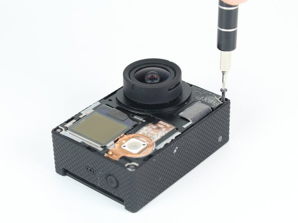
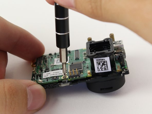
Now that the faceplate is off, it is time to remove the 4 screws on each corner.
-
Use the T4 tool bit from the iFixit toolkit in order to remove the 4 screws on each corner.
-
-
-
Questo passaggio è privo di traduzione. Aiuta a tradurlo
-
Note: Make sure you remove the door cover of the USB, mini HDMI, and SD port before. Separating the motherboard will be easier.
-
Using the plastic opening tool, slowly pry open the motherboard assembly.
-
-
Questo passaggio è privo di traduzione. Aiuta a tradurlo
-
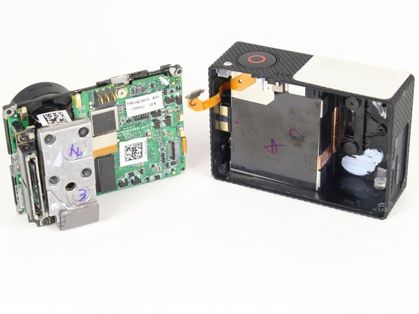
Use the spudger to gently pry off the connector of the housing to the motherboard.
-
You should now have the motherboard assembly and the housing separated.
-
-
Questo passaggio è privo di traduzione. Aiuta a tradurlo
-
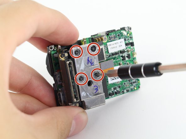
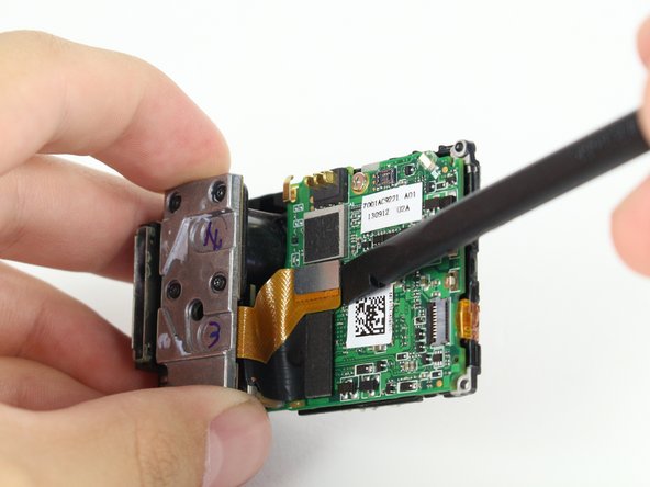
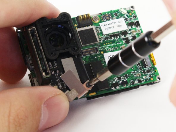
Use the spudger to remove the heat shield tape and detach the image sensor from the motherboard.
-
Using the T4 Torx toolbit, remove the 4 screws that connect the sensor to the lens.
-
Remove the silver connector of the image sensor from the motherboard using the spudger to pry it off.
-
-
Questo passaggio è privo di traduzione. Aiuta a tradurlo
-
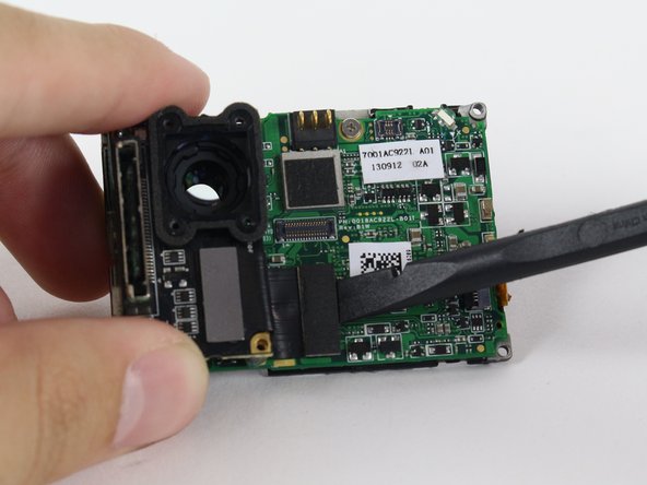
The media adapter is attached to the motherboard via 3 screws:
-
x1 T4 Torx
-
x2 Phillips #00
-
With a little prying, use the spudger to detach the media adapter's connector from the motherboard.
-
-
Questo passaggio è privo di traduzione. Aiuta a tradurlo
-
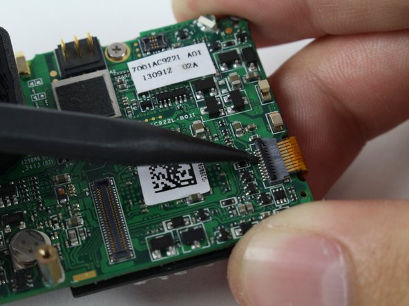
Use the spudger to lift the black tab up to unlock.
-
Then remove LCD screen connector by sliding out.
-
-
Questo passaggio è privo di traduzione. Aiuta a tradurlo
-
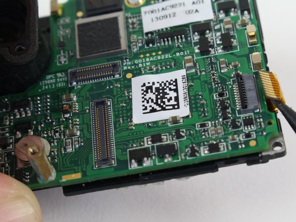
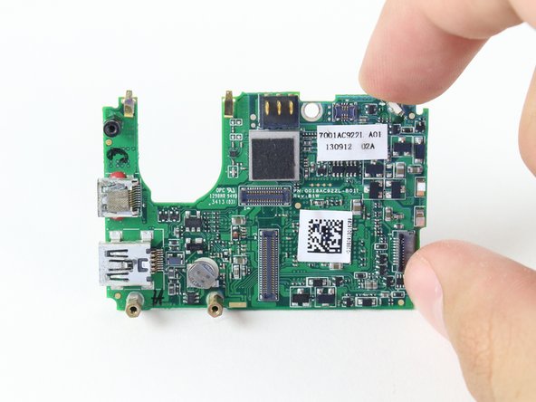
Using the Phillips head bit, remove the silver screw near the top edge of the board.
-
Separate the LCD assembly by pulling it away. You should have the bare motherboard!
-


Annulla: non ho completato questa guida.
Altre 16 persone hanno completato questa guida.
Team

Cal Poly, Team 24-7, Lancaster Spring 2015 Membro di Cal Poly, Team 24-7, Lancaster Spring 2015
CPSU-LANCASTER-S15S24G7
3 Membri
21 Guide realizzate