Questa versione può contenere modifiche errate. Passa all'ultima istantanea verificata.
Cosa ti serve
-
Questo passaggio è privo di traduzione. Aiuta a tradurlo
-
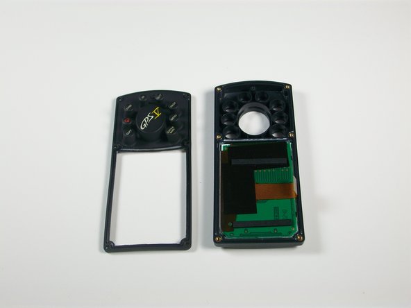
Orient the GPS V backside up.
-
With a #0 Philips screwdriver, remove six M2x0.4 black screws on the back of the unit.
-
-
Questo passaggio è privo di traduzione. Aiuta a tradurlo
-
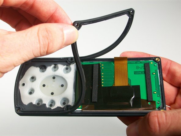
With the spudger, gently pry the back plate off the unit starting at the corners.
-
Open the back plate about 35°, use the antenna side act like a hinge.
-
-
Questo passaggio è privo di traduzione. Aiuta a tradurlo
-
Locate the white 8-pin connector on the logic board and disconnect it.
-
Open the device all the way, making sure to not disconnect the brown antenna wire.
-
-
Questo passaggio è privo di traduzione. Aiuta a tradurlo
-
With a #1 Philips screwdriver, remove the silver M2x0.4 screw on the logic board near the brown wire.
-
-
-
Questo passaggio è privo di traduzione. Aiuta a tradurlo
-
Locate the ribbon connector on the logic board.
-
With the spudger, gently apply pressure to both sides of the brown connector lock until it pushes out.
-
With the spudger, gently work the ribbon cable out of the connector until it is free.
-
-
Questo passaggio è privo di traduzione. Aiuta a tradurlo
-
With the spudger, gently pry out the logic board.
-
-
Questo passaggio è privo di traduzione. Aiuta a tradurlo
-
Locate the brown wire connection on the logic board.
-
Carefully apply heat with the soldering iron while gently pulling on the brown wire.
-
Pull brown wire free of the logic board.
-
-
Questo passaggio è privo di traduzione. Aiuta a tradurlo
-
Gently pry the button pad off of the front plate.
-
-
Questo passaggio è privo di traduzione. Aiuta a tradurlo
-
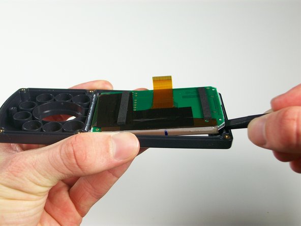
Orient the front plate of the device so the display board is facing up.
-
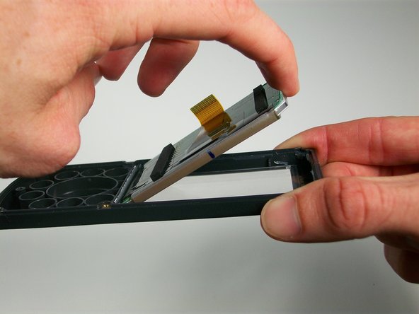
With the spudger, gently work your way around the display assembly.
-
Pry the display free of the front plate.
-
-
Questo passaggio è privo di traduzione. Aiuta a tradurlo
-
With the display removed, the front case of the Garmin GPS can be replaced.
-


Annulla: non ho completato questa guida.
Un'altra persona ha completato questa guida.
Team

Cal Poly, Team 3-25, Amido Winter 2012 Membro di Cal Poly, Team 3-25, Amido Winter 2012
CPSU-AMIDO-W12S3G25
4 Membri
4 Guide realizzate