Introduzione
If your flash settings are set correctly but your camera does not flash, you will need to replace the flash motherboard. First, you will need to remove the front and back covers. Once that is complete, you will have access to the flash motherboard.
Cosa ti serve
-
-
-
Unscrew a total of 6 4.45 mm phillips head screws using a #00 phillips head screwdriver.
-
There are 2 screws on the left side (when looking at the front of the camera).
-
There are 3 screws on the bottom
-
There is 1 screw on the right side
 Chiedi a FixBot
-
-
-
Turn to the bottom of the camera.
-
Open the memory card cover by sliding the "CARD/BATT." button up, and then pulling the cover to the left.
-
-
-
This is what the SD card/battery compartment looks like when opened.
-
Remove one 4.45mm phillips head screw from the SD card/battery compartment using a #00 phillips head screwdriver.
-
-
-
Strumento utilizzato in questo passaggio:Tweezers$4.99
-
Start from the battery compartment and remove the back cover.
-
Remove the connecting ribbon from the body of the camera using a pair of tweezers.
-
-
-
Once the ribbon connecting the back cover is removed, the back of the camera body should look like this.
-
-
-
-
-
Turn to the front of the camera.
-
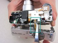
Find the flash motherboard located behind the flash assembly on the top right.
-
-
-
Use a soldering iron and a desoldering wick to disconnect the wires from the marked locations.
-
Once the cables are disconnected, you are now ready to install a new motherboard.
-
-


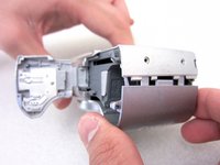
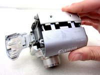


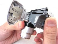
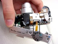


To reassemble your device, follow these instructions in reverse order.
Annulla: non ho completato questa guida.
Altre 4 persone hanno completato questa guida.

Team

Cal Poly, Team 8-6, Regan Spring 2011 Membro di Cal Poly, Team 8-6, Regan Spring 2011
CPSU-REGAN-S11S8G6
4 Membri
22 guide realizzate
