Salta al contenuto principale

EBB Can Board Replacement

Cosa ti serve

  1. EBB Can Board Replacement, PCB Install: passo 1, immagine 1 di 1
    • Tool board mount is mounted to the Turbiner, before mounting the EBB tool board to the EBB36 PCB Mount.

    • M3x8 SHCS

    • Clear Nylon washer

    • EBB36 PCB

    • M3 spacer

    • EBB PCB mount

  2. EBB Can Board Replacement, CAN Cable: passo 2, immagine 1 di 1
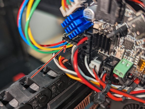
    • Molex Microfit 3.0 2x2 connector.

    • If your system was working / you are replacing toolboard, this cable needs no modifications.

    • Brown wire-Ground

    • Green wire-Vcc

    • White wire CAN H

    • Yellow wire CAN L

  3. EBB Can Board Replacement, Filament Sensor: passo 3, immagine 1 di 3 EBB Can Board Replacement, Filament Sensor: passo 3, immagine 2 di 3 EBB Can Board Replacement, Filament Sensor: passo 3, immagine 3 di 3
    • Make sure the sensor cable is plugged into LDO Runout Sensor

    • Plug runout cable from the runout sensor into the port on the EBB PCB.

  4. EBB Can Board Replacement, BL Touch: passo 4, immagine 1 di 1
    • Plugin in the 5 pin BL Touch connector

  5. EBB Can Board Replacement, Fans: passo 5, immagine 1 di 2 EBB Can Board Replacement, Fans: passo 5, immagine 2 di 2
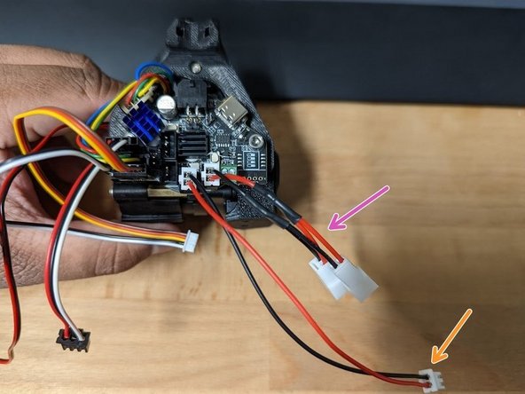
    • Hotend Fan – Heat sink fan and Extruder motor fan plug into fan splitter PCB

    • Cooling Part Fan – Both fans plug into y splitter
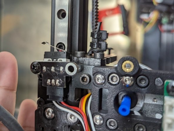
  6. EBB Can Board Replacement, X Endstop: passo 6, immagine 1 di 2 EBB Can Board Replacement, X Endstop: passo 6, immagine 2 di 2
    • 4 pin endstop cable

    • Connector has an open port to help prevent plugging in backwards. The open port is indicated with a / .

    • Ignoring this and plugging in backwards will cause damage to your 3D Printer!

    • 5v

    • Ground

    • The Signal Wire will be yellow OR white varies and is not important.

  7. EBB Can Board Replacement, Hotend Heater and Thermistor: passo 7, immagine 1 di 1
    • Loosen both screw terminals fully, then insert one wire at a time, fully tightening while holding the wire in place.

    • A proper flat blade screwdriver is required. 2mm x .4 works well.

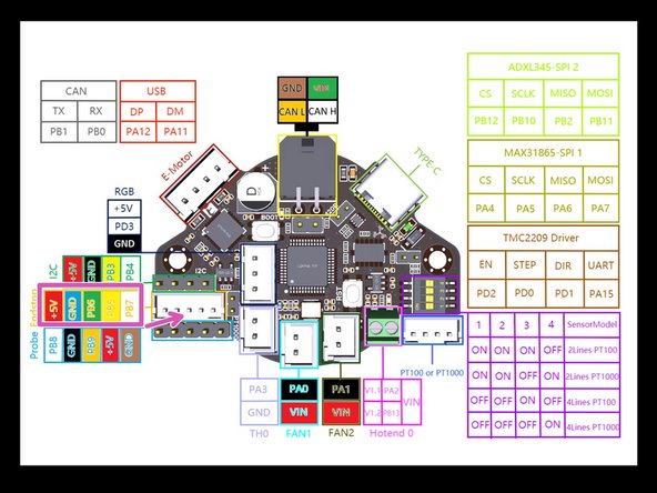
    • Connect Thermistor connector to TH0 port.

Conclusione

To reassemble your device, follow these instructions in reverse order.

Kyle Davis

Membro da: 12/02/21

241 Reputazione

1 Guida realizzata

Team

Tiny Machines 3D Membro di Tiny Machines 3D

Community

5 Membri

40 Guide realizzate

0 Commenti

Aggiungi Commento

Visualizza Statistiche:

Ultime 24 Ore: 0

Ultimi 7 Giorni: 14

Ultimi 30 Giorni: 59

Tutti i Tempi: 626